Model No: 124433-A12
Description: Lorem Ipsum is not simply random text.
- SUPERIOR QUALITY
- AFFORDABLE PRICING
- TIMELY SHIPMENT
- CUSTOMER SATISFACTION
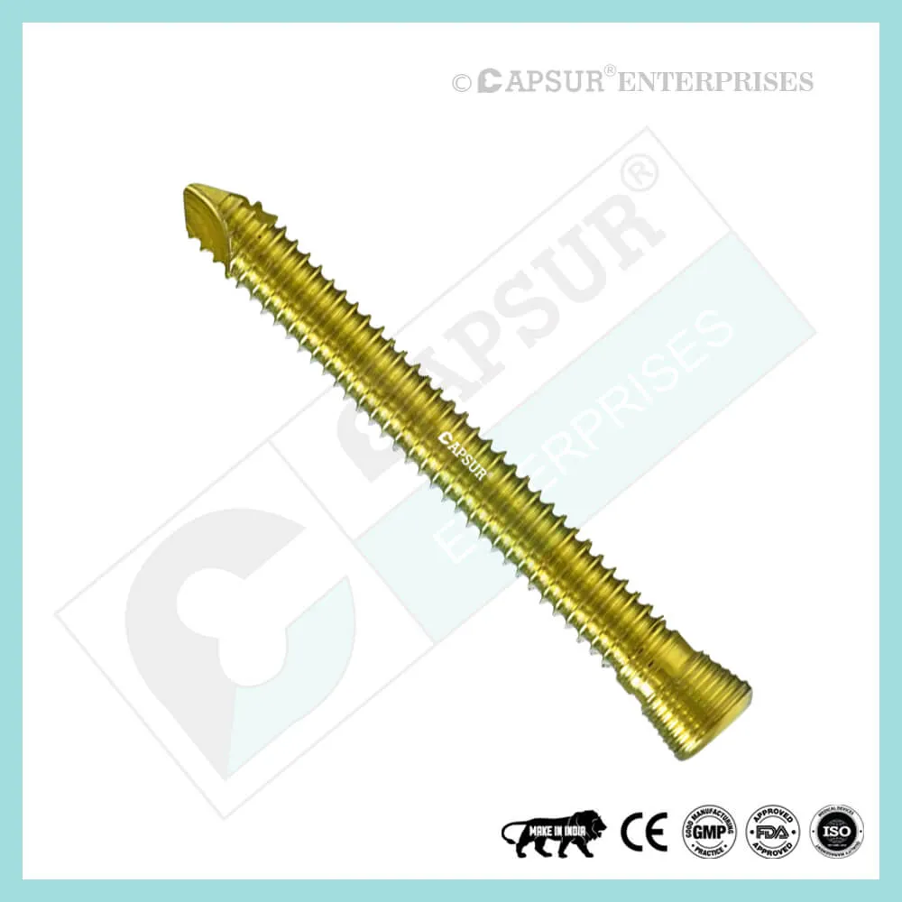
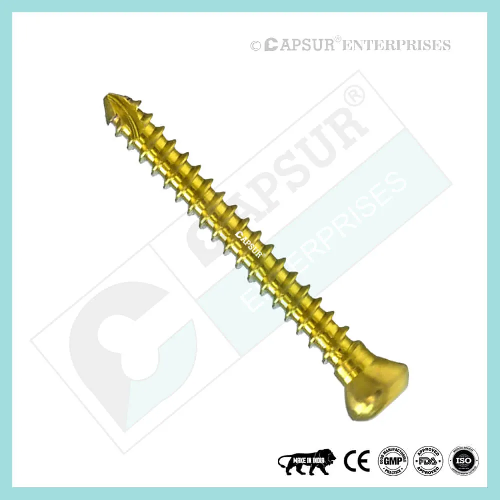
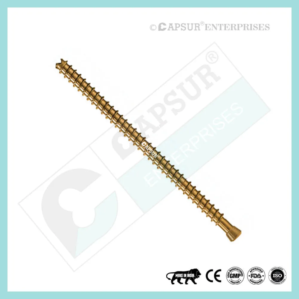
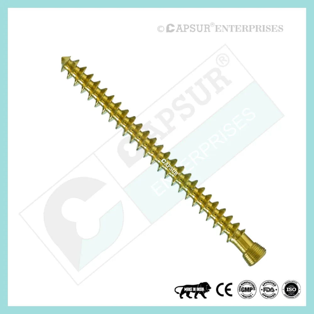
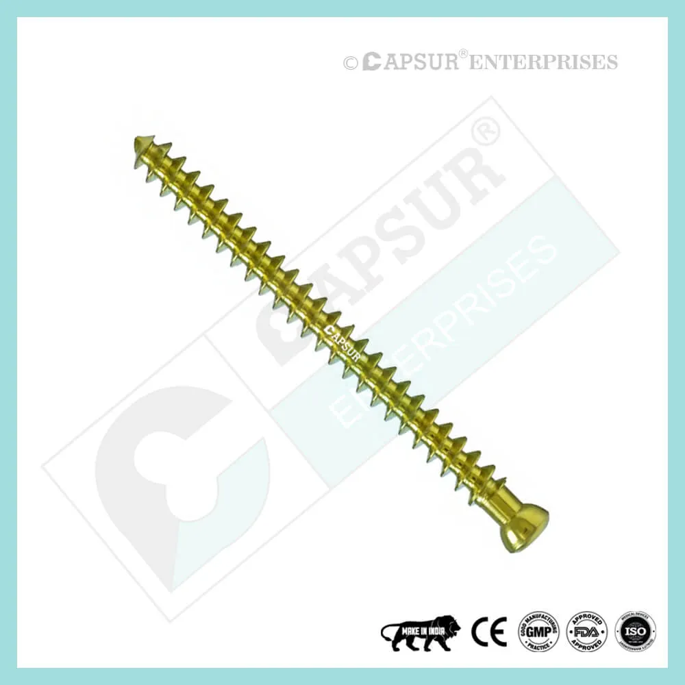
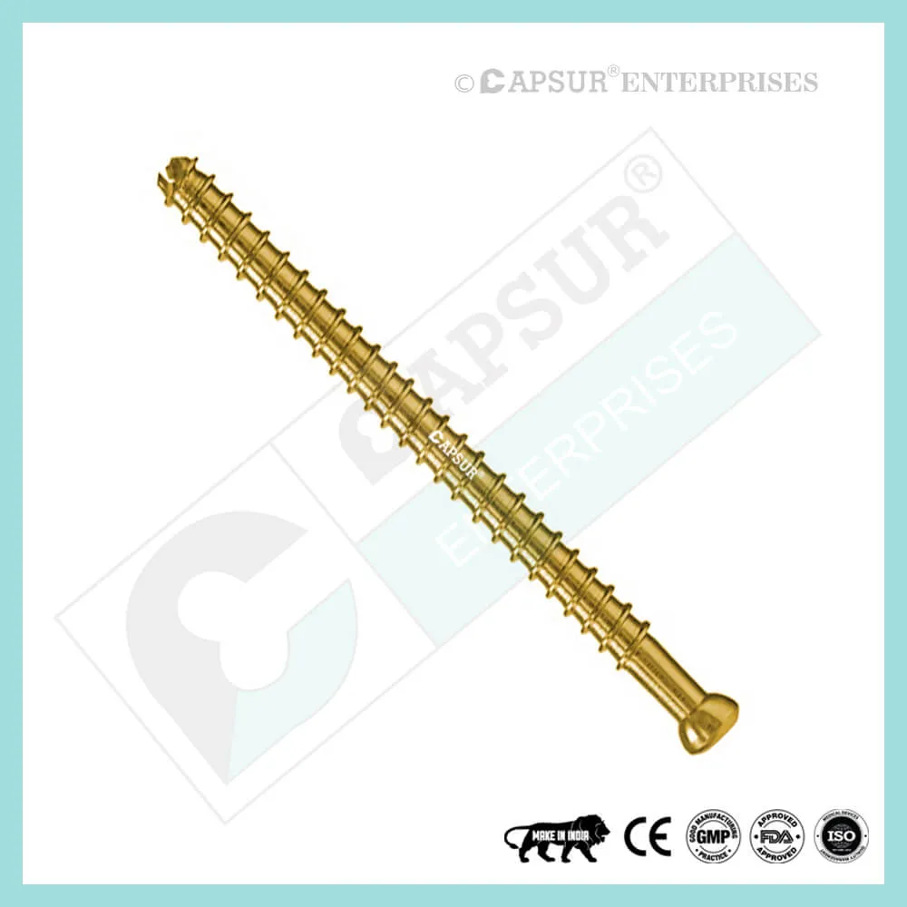
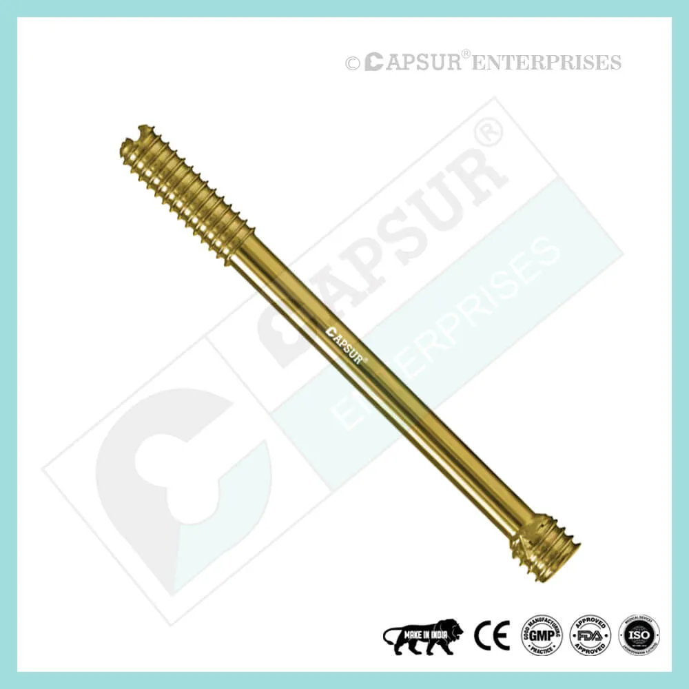
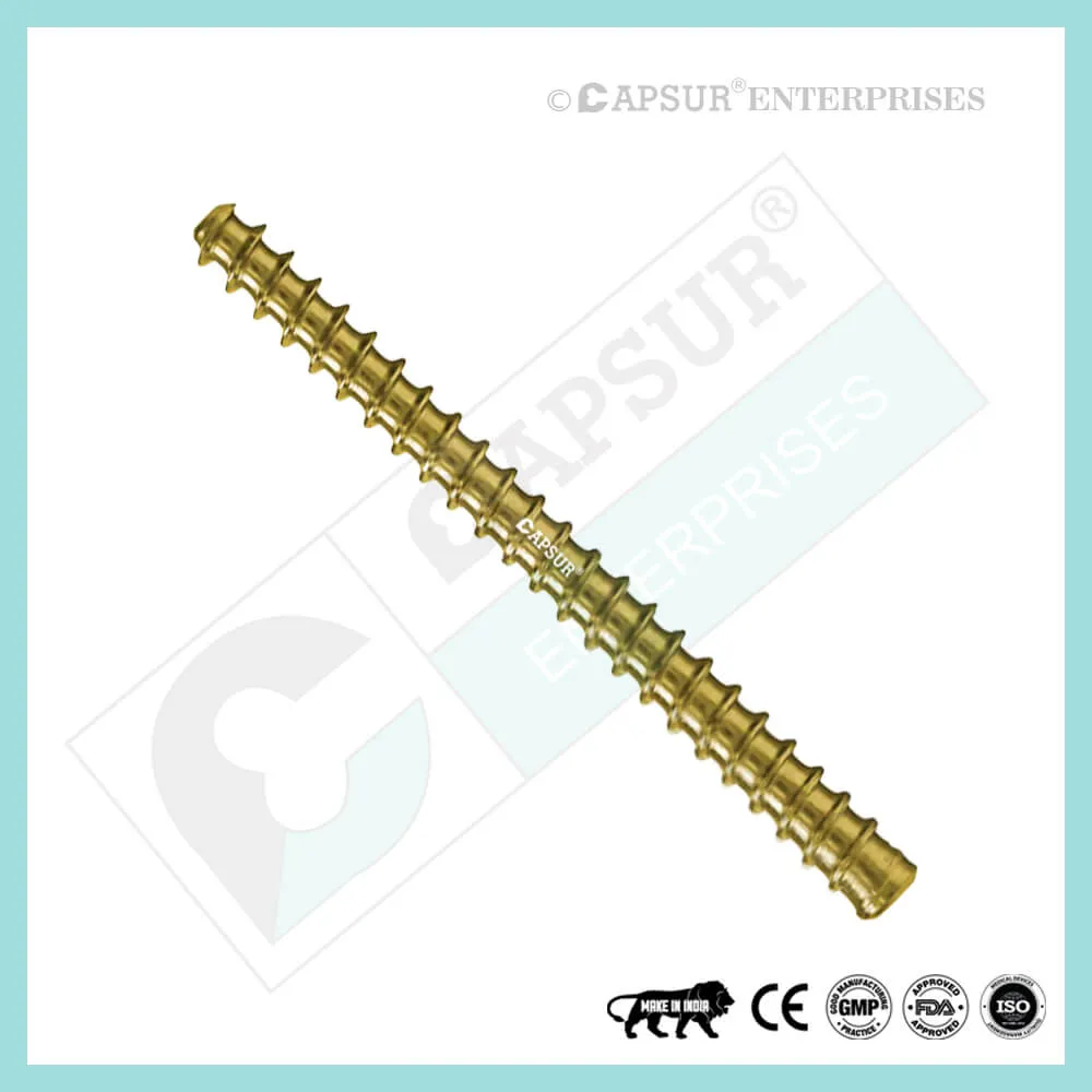
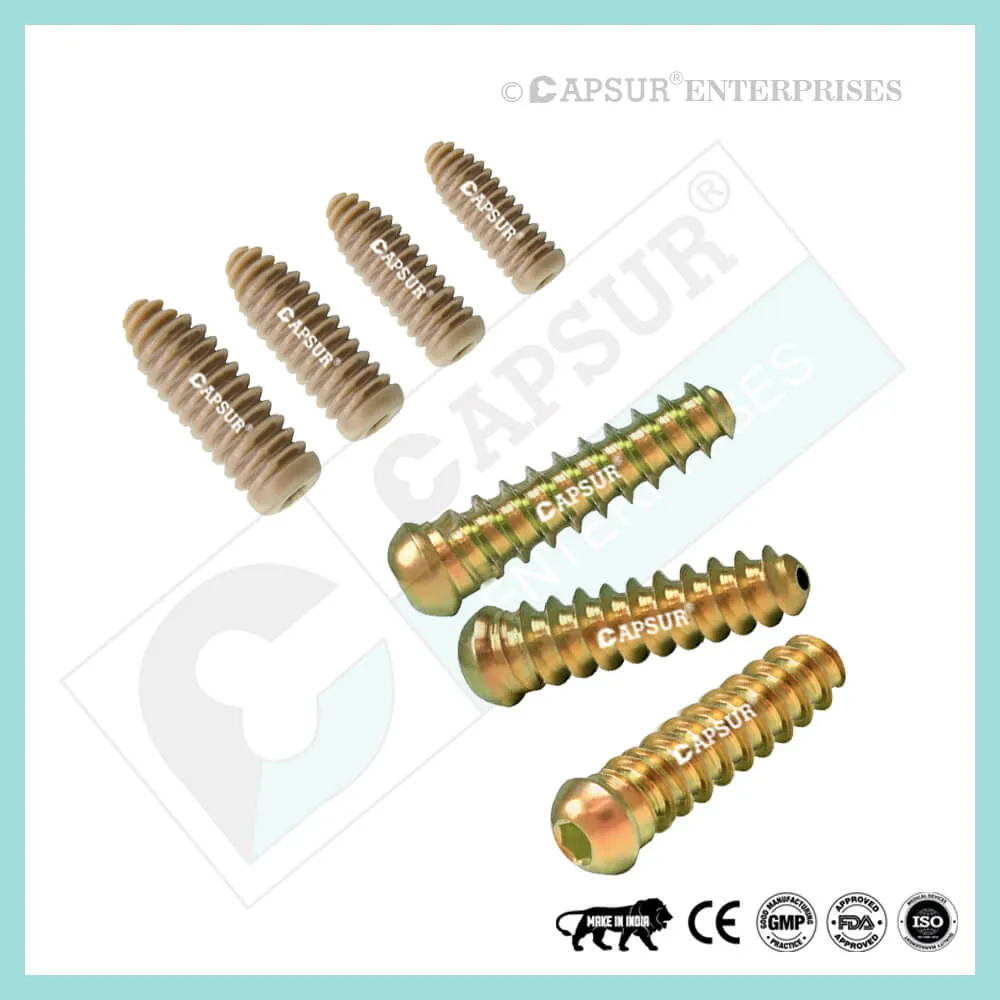
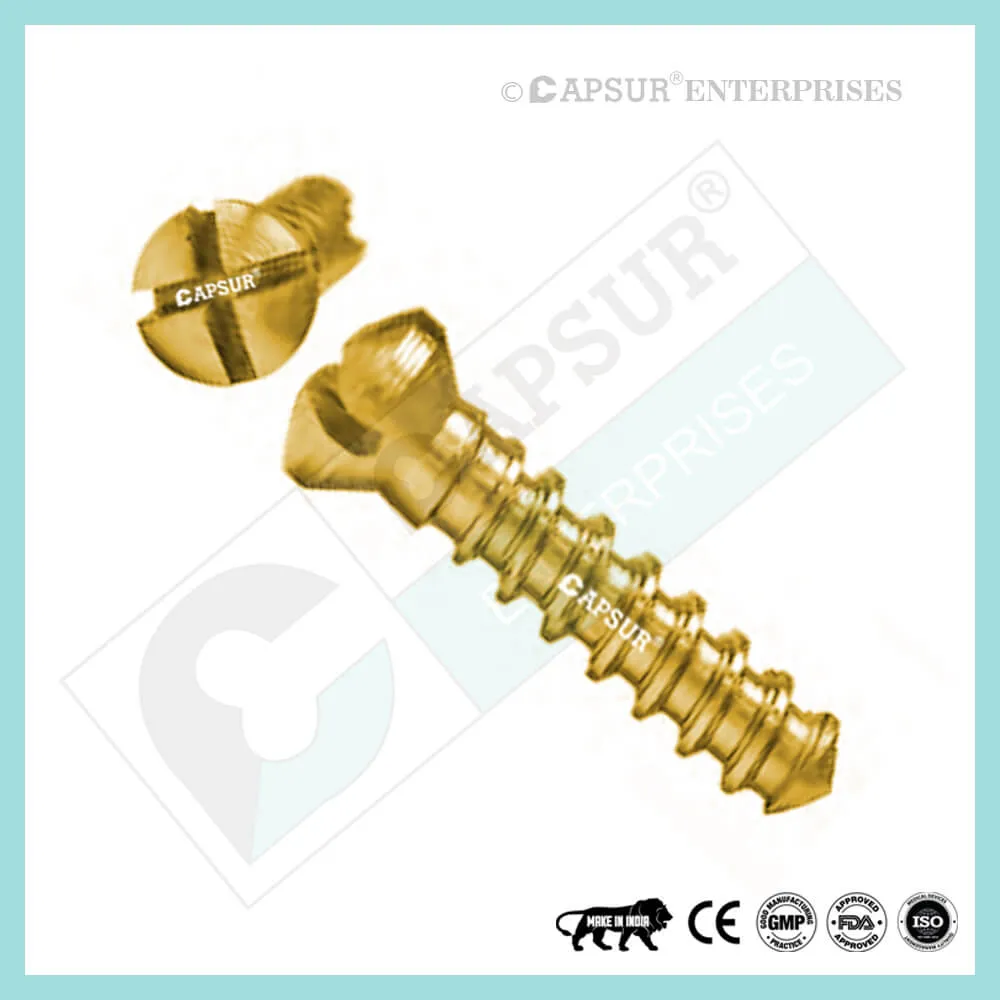
Specification for3.5 mm Headless Compression Screws, Full Thread
- Headless design: 3.5 mm headless design Compression without Heads Screw enables screw implantation with little risk of interference or soft tissue irritation in and around articular regions.
- Accurate percutaneous insertion is made easier by cannulated designs, which cause the least amount of soft tissue harm.
- Gradual compression via variable thread pitch: As the screw is advanced, the two fragments are gradually compressed because the wider thread pitch at the screw’s tip penetrates the bone faster than the finer trailing threads.
- Fully threaded: Screws with fully threaded threads have a stronger holding force, which increases stability.
- Sharp cutting flutes: The screw tip’s sharp cutting flutes make it easier to insert the screw.
- Fully and partially threaded screws come in two varieties.
- Both stainless steel and titanium are available in the 3.5 mm headless compression screw.
- 8mm, 9mm, 10mm, 11mm, 12mm, 13mm, 14mm, 16mm, 18mm, 20mm, 22mm, 24mm, 26mm, 28mm, and 30mm are the sizes of 3.5 mm Headless Compression Screws that are readily available.
- The length of this screw can be extended upon request.
- Tools like Bone Taps, Combined Drill & Tap Sleeve, Counter Sink, Depth Gauge, Drill Bits, Drill Guide, Drill Sleeve, Hollow Mill Screw Removal, Reverse Measuring Device, Screw Drivers, Screw Holding Forceps, etc. are available for this screw.
- This screw is self-tapping. While being inserted into the bone, self-tapping screws cut their own thread. When it enters the bone, it makes a tiny hole that forces the threads together tightly. This prevents vibration-induced loosening and makes it possible to disassemble the parts if necessary.
- Headless Compression Screws are available in sterile and non-sterile packaging.
Uses of 3.5 mm Headless Compression Screws, Full Thread
- Compression without Heads In accordance with their size, screws can be used for fracture repair, osteotomy, arthrodesis, joint fusion, bone reconstruction, and fracture fixation.
- Headless Compression in 3.5 mm Flowing trauma or osteotomies to the hand and foot are intended to be fixed with screws. Screw ends with self-tapping and reverse-cutting flutes make insertion and removal easier. Along its entire length, the tapered profile gains compression and increases pull-out strength.
- Headless Compression in 3.5 mm Small bones, bone fragments, and osteotomies are all intended uses for screws as fixation devices. They are not intended for soft tissue fixation or interference.
Other Useful Info of 3.5 mm Headless Compression Screws, Full Thread
Volar Scaphoid Technique for 3.5 mm Headless Compression Screw
- Approach and Insertion of the Needle
The procedure can be performed either with the arm supine on a hand table or using a conventional volar type approach. The volar traction method makes it easier to reduce a displaced fracture and allows for arthroscopy to verify the reduction’s accuracy.
Throughout, fluoroscopy is used.
A 12 or 14 gauge IV needle is then inserted on the antero-radial aspect of the wrist, just radial to and distal to the scaphoid tuberosity, to locate the entry point. This functions as both a trochar for the guide wire and a compass to create a central path along the scaphoid. After inserting the needle into the scaphotrapezial joint, it is tilted more vertically and the position is then verified on the under image intensifier. This maneuver makes the distal pole of the scaphoid more radial by gently levering on the trapezium, which ultimately makes it easier to insert screws. The entry point should be central in the lateral plane and approximately 1/3 of the way across the scaphoid from the tuberosity in the A/P plane.
- Insertion of a Guide Wire
As you drill across the fracture while continuously checking the direction on the image intensifier and making any necessary corrections, aim for the radial aspect of the proximal pole by passing the guide wire through the needle. The guide wire must not be bent, and any direction changes must be made using the needle as a guide rather than attempting to change the guide wire’s line alone.
- Calculate the Screw Length
The wire shouldn’t breach the articular surface at this point, so advance the guide wire until it stops just short of it. Once more, the position, alignment, and length are examined. With a small hemostat and blunt dissection, make a shallow incision at the wire’s entry point and deepen it all the way to the scaphoid’s distal pole.
By using the appropriate depth gauge or by inserting a second guide wire of the same length up the distal cortex of the scaphoid and subtracting the difference between the two, you can determine the length of the screw. To ensure that the proximal tip of the screw is completely buried beneath the cartilage and the cortical surface when using the volar approach, the correct screw size is 2-4 mm shorter than the measured length.
- Forward Guide Wire
To exit on the dorsal side of the wrist, advance the guide wire through the proximal pole of the scaphoid. This is a preventative measure to lessen the possibility of accidental wire withdrawal during the reaming process and screw insertion and to make it easier to remove the proximal portion in the event that the wire were to break. If it is thought that there may be a chance of rotational instability of the fracture, a second de-rotation wire can then be inserted.
- Drill
By hand or with a power drill, pass the Cannulated Profile Drill over the wire, stopping 1-2 mm short of the articular surface. Remove the 12 gauge needle. To lessen the effects of varying bone density and distraction during screw insertion, the long drill is advised.
Self-Tapping Screw Advancement
The guide wire is then removed after the self-tapping screw has been advanced over it. On the image intensifier, compression can then be radiographically verified.
Dorsal Scaphoid Technique for 3.5 mm Headless Compression Screw
- ATTITUDE AND NEEDLE INSTALLATION
At the tip of the scaphoid, close to the scapholunate ligament, is where the entry point into the proximal pole is located. This can be located between the third and fourth extensor compartments using an arthroscopy or a mini open dorsal approach. Whatever method is used, it is crucial to watch out for the guide wire transfixing an extensor tendon.
Once the entry point has been determined, insert the proper guide wire, aiming for the base of the thumb, and check the position on the fluoroscope. The subchondral surface of the distal pole of the scaphoid should be where the leading edge of the guide wire is positioned. Verify the depth and placement of the wire during imaging.
2. FRACTION STABILIZATION
The placement of a second parallel guide wire using the parallel wire guides may be beneficial if the fracture is unstable.
- FIGURE OUT SCREW LENGTH
The percutaneous screw sizer or the placement of a second wire at the entry point and the subtraction of the difference are both methods for measuring guide wire length. Due to the restricted access, the screw sizer cannot be used with the arthroscopic technique. To make sure that both screw ends are buried in the bone, deduct 4 mm from the measured length.
- DIRECT WIRE IN ADVANCE
The guide wire should be advanced through the distant cortex until it is in the subcutaneous tissues. This reduces the possibility of the guide wire accidentally being withdrawn during drilling and makes it easier to remove the wire if it breaks.
Tip: The screw shouldn’t be longer than 26 mm for the majority of adult males and 22 mm for females.
- DRILL CORTEX-FREE
With the right profile drill, the near cortex can be opened.
- FAR FRAGMENT DRILL
Next, use the long drill to enlarge the far fragment. The drill only needs to move 4-5 mm past the fracture site in order to be effective.
Advice: To lessen the effects of varying bone density and distraction during screw insertion, use a long drill.
7. SCREW INSERTION
Use the proper hex driver and the correct-sized screw to insert. Stop, remove the screw, redrill with the long drill, and then re-insert the screw if resistance is encountered during insertion or if a distraction occurs. Verify the screw’s position and length on imaging, making sure that the leading and trailing edges are buried beneath the articular surfaces. At last, take the guide wires out.
Different Types of Screws including 3.5 mm Headless Compression Screw
Locking Cortical Screws
- 2 mm Locking Cortical Screws
- 2.4 mm Locking Cortical Screws
- 2.7 mm Locking Cortical Screws
- 3.5 mm Locking Cortical Screws
- 5 mm Locking Cortical Screws
Cortical Screws
- 1.5 mm Cortical Screws
- 2 mm Cortical Screws
- 2.4 mm Cortical Screws
- 2.7 mm Cortical Screws
- 3.5 mm Cortical Screws
- 4.5 mm Cortical Screws
Locking Cancellous Screws
- 3.5 mm Locking Cancellous Screw
- 4 mm Locking Cancellous Screw
- 5 mm Locking Cancellous Screw
- 6.5 mm Locking Cancellous Screw
Cancellous Screws
- 3.5 mm Cancellous Screw
- 4 mm Cancellous Screw
- 6.5 mm Cancellous Screw
Locking Cannulated Screws
- 4 mm Locking Cannulated Screw
- 5 mm Locking Cannulated Screw
- 6.5 mm Locking Cannulated Cancellous Screw
- 7.3 mm Locking Cannulated Cancellous Screw
Cannulated Screws
- 3.5 mm Cannulated Screws (Cortical Thread)
- 4 mm Cannulated Cancellous Screws
- 4.5 mm Cannulated Cancellous Screws
- 6.5 mm Cannulated Cancellous Screws
- 7 mm Cannulated Cancellous Screws
- 7.3 mm Cannulated Cancellous Screws
Headless Screws Full Thread
- 2.5 mm Headless Compression Screws Full Thread
- 3 mm Headless Compression Screws Full Thread
- 3.5 mm Headless Compression Screws Full Thread
- 4 mm Headless Compression Screws Full Thread
- 4.5 mm Headless Compression Screws Full Thread
- 5 mm Headless Compression Screws Full Thread
- 5.5 mm Headless Compression Screws Full Thread
- 6.5 mm Headless Compression Screws Full Thread
Headless Screws Partially Thread
- 2.5 mm Headless Compression Screws Partially Thread
- 3 mm Headless Compression Screws Partially Thread
- 3.5 mm Headless Compression Screws Partially Thread
- 4 mm Headless Compression Screws Partially Thread
- 4.5 mm Headless Compression Screws Partially Thread
- 5.5 mm Headless Compression Screws Partially Thread
- 6.5 mm Headless Compression Screws Partially Thread
- 7.5 mm Headless Compression Screw Partially Thread
Interlocking Nail Screws
PFNA2 Blades
PFNA Blades
- 8 mm Proximal Cannulated Bolt
- 6.4 mm Proximal Cannulated Bolt
- 4.9 mm Locking Bolts
- 3.9 mm Locking Bolts
- 3.4 mm Locking Bolts
Interference Screws
- 5 mm Interference Screw
- 6 mm Interference Screw
- 7 mm Interference Screw
- 8 mm Interference Screw
- 9 mm Interference Screw
- 10 mm Interference Screw
Herbert Screws
- 2.5 mm Cannulated Herbert Screws
- 3 mm Cannulated Herbert Screws
- 3.5 mm Cannulated Herbert Screws
- 4.5 mm Cannulated Herbert Screws
- 5.5 mm Cannulated Herbert Screws
- 6.5 mm Cannulated Herbert Screws
Craniomaxillofacial Screws
- 1.5 mm Screw Craniomaxillofacial
- 2 mm Screw Craniomaxillofacial
- 2 mm Locking Screw Craniomaxillofacial
- 2.5 mm Screw Craniomaxillofacial
- 2.5 mm Locking Screw Craniomaxillofacial
- 2.8 mm Screw Craniomaxillofacial
- 2.8 mm Locking Screw Craniomaxillofacial
- 2.7 mm Emergency Screw
Malleolar Screws
- 3.5 mm Malleolar Screws
- 4.5 mm Malleolar Screws
The most frequently used orthopedic implants are bone screws. For various types of bones, there are numerous types and sizes of screws. The majority of bone screws are constructed from titanium or stainless steel alloys. When determining screw mechanics, it’s important to consider the outer diameter, root diameter, thread pitch, and angle.
A “3.5 mm Headless Compression Screw” is a common way to refer to a screw in orthopedics that has an outside diameter of 3.5 mm. The linear distance covered by a screw during one complete turn is known as the pitch of the screw. With each full turn, the screw moves forward by a distance equal to the space between the threads. Cortical screws have more threads because they have a lower pitch. Given the fragility of the bone, cancellous bone screws have a deeper screw to increase surface area and enhance purchase.
Screws work by converting the torque applied to tighten them into internal tension and elastic responses in the bone around them. The fracture fragments that the screw is holding together are compressed as a result. Typically, screws are inserted into holes that have been drilled to the same diameter as the root and are either self-tapping or have been tapped (threaded) beforehand. The screws must be properly inserted into the proper size drilled hole and made to withstand the insertion torque levels anticipated in cortical bone because the torque to insert cortical bone screws can be high. Large, deep threads on cancellous bone screws allow them to securely hold the spongy bone. It is uncommon for a screw to fail during insertion due to the cancellous bone’s relatively low strength, but pull out can be problematic.
3.5 mm Headless Compression Screw Risk Factor
When assessing the prognosis in each case, contraindications—which may be partial or complete—must be taken into account. Under the following circumstances, alternative management strategies may need to be taken into account:
- infections that are systemic or local, acute or chronic.
- either localized, systemic, or chronic inflammation.
- serve as a dangerous vascular, nervous, or muscular disease.
- Bone defects that would prevent the implant from being properly anchored.
- All associated illnesses that might jeopardize the implant’s success and functionality.
Warnings and Precautionary for 3.5 mm Headless Compression Screw
The surgeon and support staff should read the safety instructions in this document as well as any product-specific information in the product description, surgical techniques, and/or brochures before using the 3.5 mm Headless Compression Screw.
Screws are designed, built, and produced with the utmost care using materials of the highest quality for medical use. If these high-quality screws are used properly, they guarantee the best working outcomes. As a result, the usage guidelines and safety advice below must be followed.
The incorrect use of a screw can result in injury to the operator, patients, or other people as well as tissue damage, premature wear and tear, instrument destruction, and instrument destruction.
The operating surgeon must actively participate in the medical care of their patients. The surgeon must have a complete understanding of the instruments, their limitations, and the surgical procedure. The surgeon and the surgical team are responsible for exercising caution in the selection and use of surgical instruments. Before using implants, adequate surgical training should be obtained.
Factors that could harm the operation’s success include:
- allergies to materials implanted.
- regional bone tumors.
- osteomalacia or osteoporosis.
- metabolic disturbances and systemic disease.
- drug and alcohol abuse.
- Excessive shock-producing physical activity that exposes the implant to blows and/or heavy loads.
- Patients who lack the mental capacity to comprehend and follow instructions from a doctor.
- Unhealthy overall.
- Potential Negative Effects
The most frequent side effects following implantation are as follows:
- screw loosening that may be caused by the implant’s tissue reaction or by the fixation site’s repeated loading.
- the two stages of infection.
- additional bone fracture brought on by abnormal stress or weakened bone structure.
- a hematoma or pressure-related pressure that causes temporary or permanent neural damage.
- Hematomas from wounds and slow wound healing.
- Venous thrombosis, pulmonary embolism, and cardiac arrest are examples of vascular disease.
- heterotopically ossifying.
- suffering brought on by the 3.5 mm Headless Compression Screw.
- Implant mechanical failure, such as bending, loosening, or breakage.
- Implant migration leading to injury.
Preoperative Planning for 3.5 mm Headless Compression Screw
Following a thorough clinical evaluation of the patient, the operation is planned. X-rays are also necessary to provide a clear picture of the bony anatomy and any associated deformities. The necessary implantation tools and a full size 3.5 mm Headless Compression Screw must be on hand at the time of the procedure.
The potential risks and complications related to the use of implants should be discussed with the patient by the clinician. If the patient has allergies to any of the implant materials, it is crucial to know this before surgery. Additionally, the patient needs to be made aware that the device’s performance cannot be guaranteed because problems may reduce its lifespan.
3.5 mm Headless Compression Screw Precautions
During reprocessing, verify that the instruments are functional and look for wear. Before using, replace any worn-out or broken instruments.
It is advised to use the tools designated for this screw.
Use caution when handling equipment, and put used bone-cutting tools in a sharps container.
Always use suction and irrigation to remove any debris that may be produced during implantation or removal.
3.5 mm Headless Compression Screw Warnings
the 3.5 mm Headless Compression When excessive forces are applied, a screw may break while in use. We advise that, whenever possible and practical for the particular patient, the broken part should be removed. The surgeon will ultimately decide whether to remove the broken part based on the risk involved. Be aware that implants lack native bone’s tensile strength. Implants that are subjected to heavy loads may fail.
Sharp edges or moving joints on tools, screws, and cut plates could rip or pinch the user’s glove or skin.
Make sure to get rid of any fragments that weren’t surgically fixed.
The final decision to remove an implant rests with the surgeon, but we advise that fixation devices be taken out as soon as it is safe and practical for the particular patient and after their purpose as a healing aid has been fulfilled. To prevent refracture, postoperative care should be sufficient after implant removal.
3.5 mm Headless Compression Screw General Adverse Events
There are risks, side effects, and adverse events associated with all major surgical procedures. While there are many possible reactions, the following are some of the most frequent ones: issues related to anesthesia and patient positioning (such as nausea, vomiting, dental injuries, neurological impairments, etc.), thrombosis, embolism, infection, damage to nerve and/or tooth roots or other critical structures, such as blood vessels, excessive bleeding, damage to soft tissues, including swelling, abnormal scar formation, functional impairment of the musculoskeletal system, and pain.
| 3.5 mm Headless Compression Screws, Full Thread |
|---|