Femoral Neck Fracture ORIF with Dynamic Condylar Screw
PRINCIPLES
Subcapital and displaced transcervical fractures are unstable. Their prognosis is largely the same, and should internal fixation be chosen as the course of treatment, they will be discussed together in order to determine the best reduction strategy and fixation option.
A cannulated screw is inserted above and parallel in both planes to the Dynamic Condylar Screw plate if additional rotational stability is desired in addition to the Dynamic Hip Screw. It must be parallel in order to preserve the implant’s ability to slide.
Positioning of the patient
On the fracture table, the patient is positioned supine for closed reduction. The contralateral, unharmed leg is positioned on a leg holder, and the ipsilateral arm is raised in a sling.
In the event that closed reduction is unsuccessful, the patient may be moved to a standard table for open reduction.
Control of the C-arm image intensifier is essential during surgery.
Approaches for open reduction
The following methods for open reduction may be used in this procedure:
front-facing approach
Iliofemoral technique
REDUCTION
Closed reduction
Generally, reduction can be achieved by gently rotating the fractured leg internally while controlling the image intensifier. With an image intensifier, the reduction must be examined in both the lateral and AP views.
On occasion, applying anteroposterior pressure to the thigh may aid in minimizing retroversion.
Open reduction should be tried if gentle closed reduction fails.
Anatomical alignment ought to be restored by the reduction.
Open reduction
An open reduction must be performed if the closed reduction fails. Under clear visual observation, the neck fracture is reduced.
As soon as the capsule has been opened while traction is being applied, the head is moved using hooks or K-wires that are inserted to serve as joysticks until anatomical reduction is achieved.
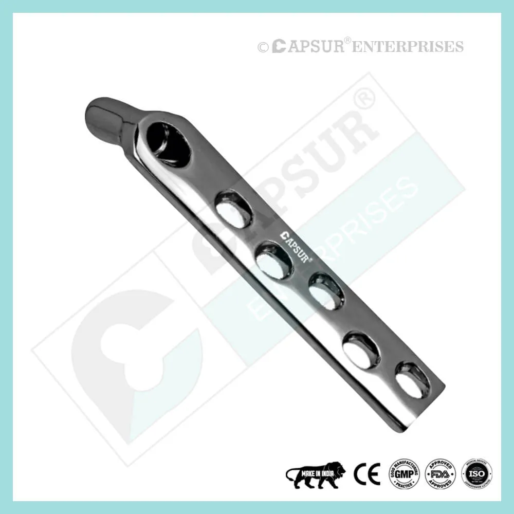
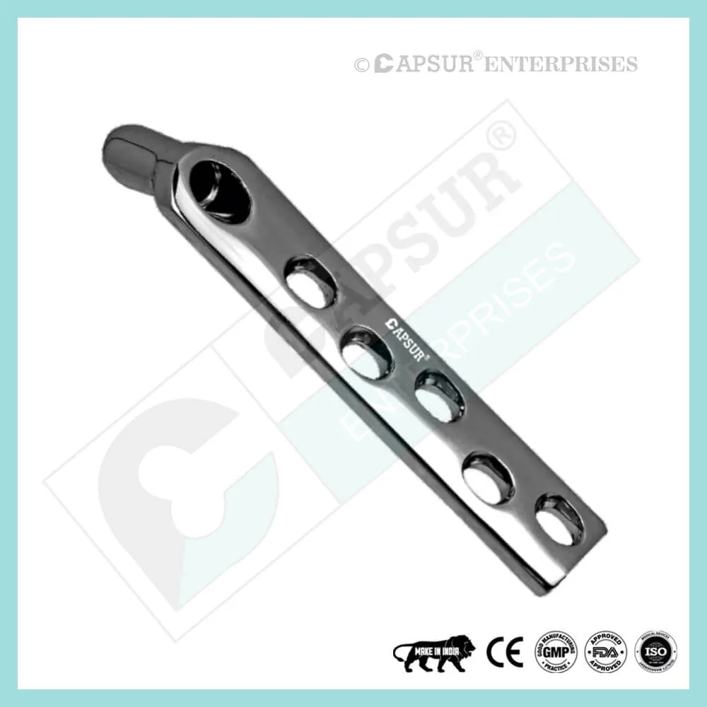
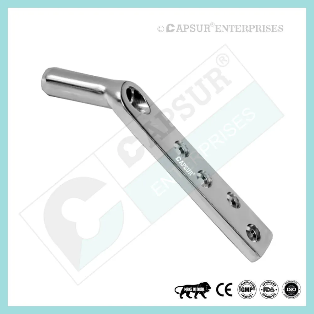
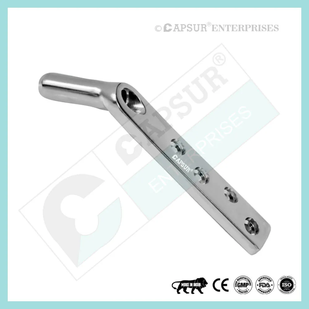
FIXATION WITH Dynamic Condylar Screw Plate
Technique of insertion
A guide wire must first be placed on the neck and driven into the head as the first step. Slide the guide wire parallel to the neck’s axis while the C-arm is set up to reveal it, then gently tap it into the head.
Make sure the wire subtends the neck’s CCD (collum-center-diaphysis) angle with the C-arm in the AP. You can insert the guide wire for the screw easier using this.
Insertion of the guide wire
Select the appropriate aiming tool based on the neck’s CCD angle. Use the image intensifier to check its location in the AP view.
Advance the guide wire into the subchondral bone of the head through the aiming device, stopping 10 mm short of the joint.
The guide wire should be placed through the middle of the head, along the axis of the neck, and advanced to within 5 mm of the subchondral bone in both the AP and lateral planes.
Determination of the length of the Dynamic Condylar Screw
With the aid of the measuring tool, ascertain the Dynamic Condylar Screw’s length. Choose a screw that is 10 mm shorter than the length that was measured.
Drilling
The screw length can be selected by adjusting the cannulated triple reamer. Create a hole in the plate sleeve and screw.
Dynamic Condylar Screw insertion
It is mounted on the handle and inserted over the guide wire using the proper Dynamic Condylar Screw. It is inserted into the bone by turning the handle. Push gently; otherwise, you risk distracting the fracture.
It is best to use the tap to precut the screw thread in young patients with hard bone. Otherwise, the screw might not advance, and if you twist the proximal fragment while trying to insert the screw, you might actually displace the fracture.
The T-handle of the insertion piece should be parallel to the long axis of the bone once the screw has reached its final position (checked with the image intensifier: 10 mm short of the subchondral bone in the AP and lateral). This will ensure that the plate is in the right place.
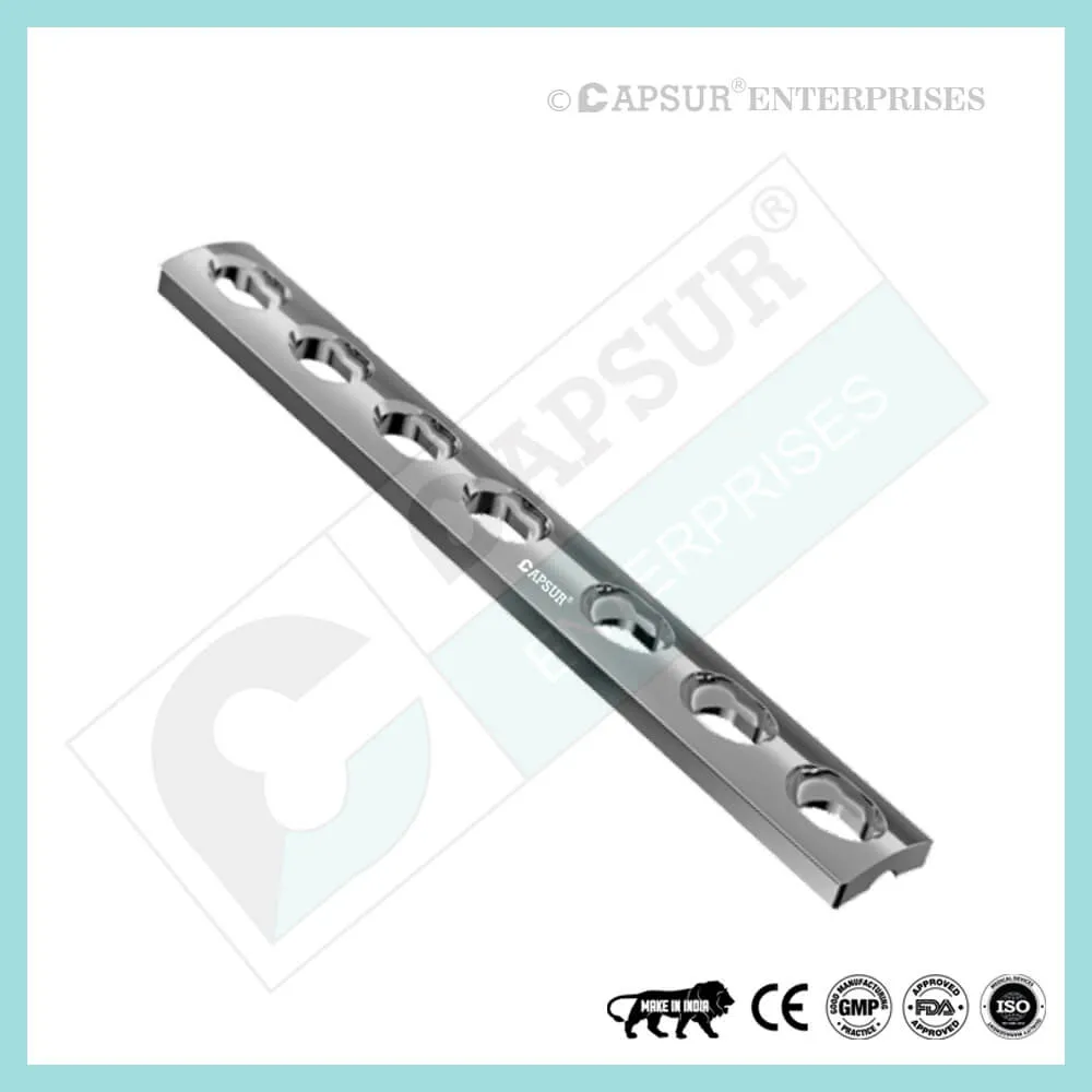
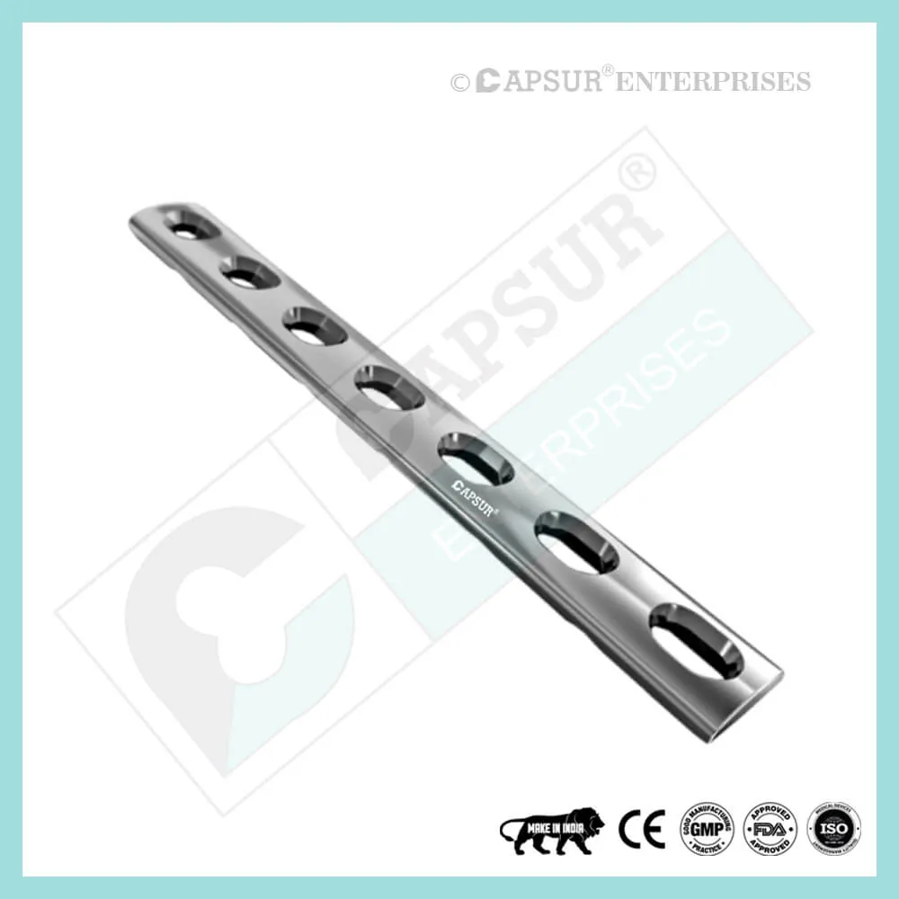
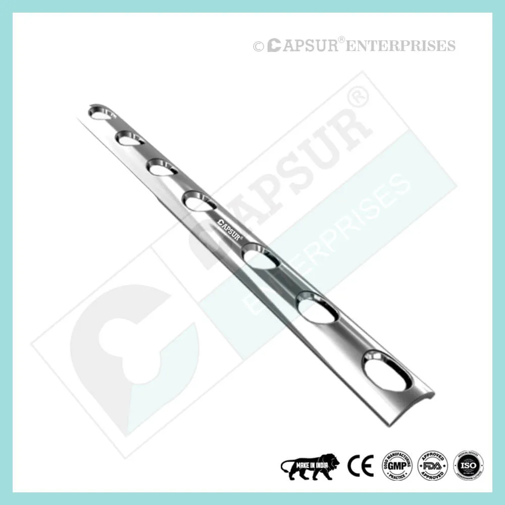
Fixation of the Dynamic Condylar Screw Plate
In most cases, a Dynamic Condylar Screw plate with two holes and the preoperatively determined CCD angle will be used. Slide the CCD-angle-appropriate plate over the guide wire and securely attach it to the screw. Then use the impactor to seat it into place over the screw.
Importance of screw position in intertrochanteric femoral fractures treated by Dynamic Condylar Screw
Background
When an intertrochanteric femoral fracture is treated with a dynamic Condylar screw, it is generally accepted that a tip-apex distance greater than 25 mm is a strong predictor of screw cut-out. This retrospective study’s objective was to assess the placement of the screw in the femoral head and its impact on cut-out failure, particularly in patients with unfavorable tip-apex distance.
Clients and techniques
In order to divide the 65 patients (42 men and 23 women; mean age, 57.6 years) who underwent dynamic Condylar screw surgery for intertrochanteric femoral fractures into two groups, it was taken into account whether the tip-apex distance was less than 25 mm in Group A (14 patients) or more than 25 mm in Group B (51 patients). Age and gender of the patient, the length of follow-up, the type of fracture, the degree of osteoporosis, the fracture’s reduction quality, the location of the screw in the femoral head, the number of patients who experienced cut-out failure, and the Harris hip score were all compared.
Results
There was a 41.7 month follow-up period on average. In Group A, the mean tip-apex distance was 17.14 mm, whereas in Group B, it was 36.67 mm. Three (5.8%) and one (7.1%) patients in Group B, respectively, had screw cut-outs. No statistically significant differences were found between the two groups in terms of the study data, with the exception of screw position. In Group B, the screw was positioned centrally in the femoral head, whereas in Group A, the screw was positioned more inferiorly (p = 0.045) on frontal and more posteriorly (p = 0.013) on sagittal planes. The screw’s position, which was located in the femoral head more superiorly and anteriorly after an acceptable fracture reduction, was shared by the three patients in Group B with screw cut-outs.
Conclusions
The tip-apex distance is increased by inserting the screw in the femoral head from the side. However, in unstable intertrochanteric fractures, posterior and inferior locations may help to support the posteromedial cortex and calcar femoral and lower the risk of cut-out failure.
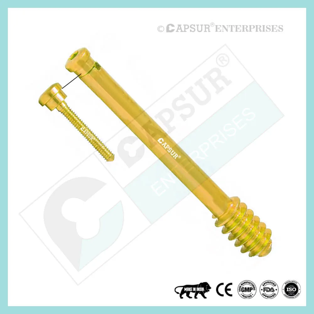
Different Types of Screws including Dynamic Condylar Screw
Locking Cortical Screws
- 2 mm Locking Cortical Screws
- 2.4 mm Locking Cortical Screws
- 2.7 mm Locking Cortical Screws
- 3.5 mm Locking Cortical Screws
- 5 mm Locking Cortical Screws
Cortical Screws
- 1.5 mm Cortical Screws
- 2 mm Cortical Screws
- 2.4 mm Cortical Screws
- 2.7 mm Cortical Screws
- 3.5 mm Cortical Screws
- 4.5 mm Cortical Screws
Locking Cancellous Screws
- 3.5 mm Locking Cancellous Screw
- 4 mm Locking Cancellous Screw
- 5 mm Locking Cancellous Screw
- 6.5 mm Locking Cancellous Screw
Cancellous Screws
- 3.5 mm Cancellous Screw
- 4 mm Cancellous Screw
- 6.5 mm Cancellous Screw
- Locking Cannulated Screws
- 4 mm Locking Cannulated Screw
- 5 mm Locking Cannulated Screw
- 6.5 mm Locking Cannulated Cancellous Screw
- 7.3 mm Locking Cannulated Cancellous Screw
Cannulated Screws
- 3.5 mm Cannulated Screws (Cortical Thread)
- 4 mm Cannulated Cancellous Screws
- 4.5 mm Cannulated Cancellous Screws
- 6.5 mm Cannulated Cancellous Screws
- 7 mm Cannulated Cancellous Screws
- 7.3 mm Cannulated Cancellous Screws
Headless Screws Full Thread
- 2.5 mm Headless Compression Screws Full Thread
- 3 mm Headless Compression Screws Full Thread
- 3.5 mm Headless Compression Screws Full Thread
- 4 mm Headless Compression Screws Full Thread
- 4.5 mm Headless Compression Screws Full Thread
- 5 mm Headless Compression Screws Full Thread
- 5.5 mm Headless Compression Screws Full Thread
- 6.5 mm Headless Compression Screws Full Thread
Headless Screws Partially Thread
- 2.5 mm Headless Compression Screws Partially Thread
- 3 mm Headless Compression Screws Partially Thread
- 3.5 mm Headless Compression Screws Partially Thread
- 4 mm Headless Compression Screws Partially Thread
- 4.5 mm Headless Compression Screws Partially Thread
- 5.5 mm Headless Compression Screws Partially Thread
- 6.5 mm Headless Compression Screws Partially Thread
- 7.5 mm Headless Compression Screw Partially Thread
Interlocking Nail Screws
PFNA2 Blades
PFNA Blades
- 8 mm Proximal Cannulated Bolt
- 6.4 mm Proximal Cannulated Bolt
- 4.9 mm Locking Bolts
- 3.9 mm Locking Bolts
- 3.4 mm Locking Bolts
Interference Screws
- 5 mm Interference Screw
- 6 mm Interference Screw
- 7 mm Interference Screw
- 8 mm Interference Screw
- 9 mm Interference Screw
- 10 mm Interference Screw
Herbert Screws
- 2.5 mm Cannulated Herbert Screws
- 3 mm Cannulated Herbert Screws
- 3.5 mm Cannulated Herbert Screws
- 4.5 mm Cannulated Herbert Screws
- 5.5 mm Cannulated Herbert Screws
- 6.5 mm Cannulated Herbert Screws
Craniomaxillofacial Screws
- 1.5 mm Screw Craniomaxillofacial
- 2 mm Screw Craniomaxillofacial
- 2 mm Locking Screw Craniomaxillofacial
- 2.5 mm Screw Craniomaxillofacial
- 2.5 mm Locking Screw Craniomaxillofacial
- 2.8 mm Screw Craniomaxillofacial
- 2.8 mm Locking Screw Craniomaxillofacial
- 2.7 mm Emergency Screw
Malleolar Screws
- 3.5 mm Malleolar Screws
- 4.5 mm Malleolar Screws
The most frequently used orthopedic implants are bone screws. For various types of bones, there are numerous types and sizes of screws. The majority of bone screws are constructed from titanium or stainless steel alloys. When determining screw mechanics, it’s important to consider the outer diameter, root diameter, thread pitch, and angle.
A screw’s outer diameter is commonly used in orthopedics to describe the screw; for instance, a “12.5 mm Dynamic Condylar Screw” has an outer diameter of 12.5 mm. The linear distance covered by a screw during one complete turn is known as the pitch of the screw. With each full turn, the screw moves forward by a distance equal to the space between the threads. Cortical screws have more threads because they have a lower pitch. Given the fragility of the bone, cancellous bone screws have a deeper screw to increase surface area and enhance purchase.
Screws work by converting the torque applied to tighten them into internal tension and elastic responses in the bone around them. The fracture fragments that the screw is holding together are compressed as a result. Typically, screws are inserted into holes that have been drilled to the same diameter as the root and are either self-tapping or have been tapped (threaded) beforehand. The screws must be properly inserted into the proper size drilled hole and made to withstand the insertion torque levels anticipated in cortical bone because the torque to insert cortical bone screws can be high. Large, deep threads on cancellous bone screws allow them to securely hold the spongy bone. It is uncommon for a screw to fail during insertion due to the cancellous bone’s relatively low strength, but pull out can be problematic.
Dynamic Condylar Screw Risk Factor
When assessing the prognosis in each case, contraindications—which may be partial or complete—must be taken into account. Under the following circumstances, alternative management strategies may need to be taken into account:
- infections that are systemic or local, acute or chronic.
- either localized, systemic, or chronic inflammation.
- serve as a dangerous vascular, nervous, or muscular disease.
- Bone defects that would prevent the implant from being properly anchored.
- All associated illnesses that might jeopardize the implant’s success and functionality.
Warnings and Precautionary for Dynamic Condylar Screw
The surgeon and support staff should read the safety instructions in this document as well as any product-specific information in the product description, surgical techniques, and/or brochures before using Dynamic Condylar Screw.
Screws are designed, built, and produced with the utmost care using materials of the highest quality for medical use. If these high-quality screws are used properly, they guarantee the best working outcomes. As a result, the usage guidelines and safety advice below must be followed.
The incorrect use of a screw can result in injury to the operator, patients, or other people as well as tissue damage, premature wear and tear, instrument destruction, and instrument destruction.
The operating surgeon must actively participate in the medical care of their patients. The surgeon must have a complete understanding of the instruments, their limitations, and the surgical procedure. The surgeon and the surgical team are responsible for exercising caution in the selection and use of surgical instruments. Before using implants, adequate surgical training should be obtained.
Factors that could harm the operation’s success include:
- allergies to materials implanted.
- regional bone tumors.
- osteomalacia or osteoporosis.
- metabolic disturbances and systemic disease.
- drug and alcohol abuse.
- Excessive shock-producing physical activity that exposes the implant to blows and/or heavy loads.
- Patients who lack the mental capacity to comprehend and follow instructions from a doctor.
- Unhealthy overall.
- Potential Negative Effects
The most frequent side effects following implantation are as follows:
- screw loosening that may be caused by the implant’s tissue reaction or by the fixation site’s repeated loading.
- the two stages of infection.
- additional bone fracture brought on by abnormal stress or weakened bone structure.
- a hematoma or pressure-related pressure that causes temporary or permanent neural damage.
- Hematomas from wounds and slow wound healing.
- Venous thrombosis, pulmonary embolism, and cardiac arrest are examples of vascular disease.
- heterotopically ossifying.
- Due to the Dynamic Condylar Screw’s presence, there is pain and discomfort.
- Implant mechanical failure, such as bending, loosening, or breakage.
- Implant migration leading to injury.
- Surgical Preparation for Dynamic Condylar Screw
- Following a thorough clinical evaluation of the patient, the operation is planned. X-rays are also necessary to provide a clear picture of the bony anatomy and any associated deformities. Along with a full size of the Dynamic Condylar Screw, the appropriate implantation tools must be on hand at the time of the procedure.
- The potential risks and complications related to the use of implants should be discussed with the patient by the clinician. If the patient has allergies to any of the implant materials, it is crucial to know this before surgery. Additionally, the patient needs to be made aware that the device’s performance cannot be guaranteed because problems may reduce its lifespan.
Dynamic Condylar Screw Precautions
During reprocessing, verify that the instruments are functional and look for wear. Before using, replace any worn-out or broken instruments.
It is advised to use the tools designated for this screw.
Use caution when handling equipment, and put used bone-cutting tools in a sharps container.
Always use suction and irrigation to remove any debris that may be produced during implantation or removal.
Dynamic Condylar Screw Warnings
When subjected to excessive forces, Dynamic Condylar Screws have the potential to break while in use. We advise that the broken part be removed whenever possible and practical for the particular patient, though the surgeon will ultimately decide whether to do so based on the risk involved. Be aware that implants lack the natural bone’s strength. Significant loads may cause implants to fail.
The user’s glove or skin may be pinched or torn by the sharp edges or moving joints of some instruments, screws, and cut plates.
Be sure to get rid of any fragments that weren’t fixed during surgery.
While the surgeon will ultimately decide whether to remove the implant, we advise that fixation devices be taken out as soon as it is safe and practical for the specific patient and after their purpose as a healing aid has been fulfilled. To prevent refracture, implant removal should be followed by adequate post-operative care.
Dynamic Condylar Screw General Adverse Events
There are risks, side effects, and adverse events associated with all major surgical procedures. While there are many possible reactions, the following are some of the most frequent ones: issues related to anesthesia and patient positioning (such as nausea, vomiting, dental injuries, neurological impairments, etc.), thrombosis, embolism, infection, damage to nerve and/or tooth roots or other critical structures, such as blood vessels, excessive bleeding, damage to soft tissues, including swelling, abnormal scar formation, functional impairment of the musculoskeletal system, and pain.