
Model No: 124433-A12
Description:
- SUPERIOR QUALITY
- AFFORDABLE PRICING
- TIMELY SHIPMENT
- CUSTOMER SATISFACTION
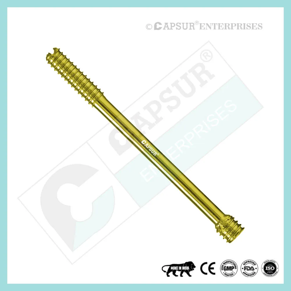
Specification for PFNA2 Blades
- One element achieves both rotational and angular stability.
- Compaction of cancellous bone: Inserting the PFNA2 Blade compacts the cancellous bone, supplying additional anchoring, which is crucial in osteoporotic bone in particular.
- For maximum compaction and the best hold in bone, use a large surface and a growing core diameter. Biomechanical research has shown that the increased stability brought on by the bone compacting around the PFNA2 blade prevents rotation and varus collapse. According to biomechanical tests, the PFNA2 blade had a significantly higher cut-out resistance than commonly employed screw systems.
- The PFNA2 blade is automatically locked to prevent rotation of the blade and femoral head when it is inserted through a lateral incision.
- Blade lengths are 70mm, 75mm, 80mm, 85mm, 90mm, 95mm, 100mm, 105mm, 110mm, 115mm, and 120mm.
- Pure Titanium and Stainless Steel 316L are used to make the PFNA2 Blade.
Uses of PFNA2 Blades
- By compacting the cancellous bone with the PFNA2 Blade, more anchoring is provided, which is crucial in osteoporotic bone.
Other Useful Info of PFNA2 Blades
PFNA2 Surgical Techniques
- Determine entry point
Given that the ML angle of the PFNA2 is 5°, the entry point of the PFNA2 in AP view is on the tip of the greater trochanter or just lateral to the tip in the curved extension of the medullary cavity.The entry point lines up with the intramedullary canal’s axis in lateral view.
- Insert guide wire
In the power tool, secure the guide wire. The guide wire can also be manually inserted using the universal chuck with T-handle. Put the drill sleeve and the protection sleeve in place at the insertion point. Through the drill sleeve and protection sleeve, thread the guide wire. Power tool and drill sleeve should be removed.Leave the first guide wire in place and place a second guide wire through one of the numerous holes in the drill sleeve to correct the guide wire’s placement.
- Open femur with flexible drill bit
Drill the cavity for the proximal portion of the PFNA2 nail using the power tool while guiding the flexible cannulated drill bit through the protection sleeve over the guide wire. Remove the guide wire, protection sleeve, and drill bit. It is advised to carefully open the femur with a power tool operating at high speed or by hand. Avoid lateral movements or strong compression forces to prevent dislocation of the fracture fragments.
- Establish a point of entry
Given that the ML angle of the PFNA2 is 5°, the entry point of the PFNA2 in AP view is on the tip of the greater trochanter or just lateral to the tip in the curved extension of the medullary cavity.
The entry point lines up with the intramedullary canal’s axis in lateral view.
Techniques for PFNA2 Surgery 1: Inserting a Guide Wire 2.
In the power tool, secure the guide wire. The guide wire can also be manually inserted using the universal chuck with T-handle.
Put the drill sleeve and the protection sleeve in place at the insertion point. Through the drill sleeve and protection sleeve, thread the guide wire. Power tool and drill sleeve should be removed.
Leave the first guide wire in place and place a second guide wire through one of the numerous holes in the drill sleeve to correct the guide wire’s placement.
- Open the femur with a flexible drill bit from PFNA2 surgical techniques 2.
Drill the cavity for the proximal portion of the PFNA2 nail using the power tool while guiding the flexible cannulated drill bit through the protection sleeve over the guide wire. Remove the guide wire, protection sleeve, and drill bit.
It is advised to carefully open the femur with a power tool operating at high speed or by hand. Avoid lateral movements or strong compression forces to prevent dislocation of the fracture fragments.
Surgery Techniques 3 PFNA2
- Ream the medullary canal
Use the medullary reamer to, if necessary, enlarge the femoral canal to the desired diameter. Verify fracture reduction while controlling the image intensifier.Reaming rod insertion: Set the reaming rod’s insertion depth before inserting it into the medullary canal. The final distal position of the long PFNA2 Nail is determined by how well the tip is positioned in the medullary canal. Reaming: Begin by reaming the 8.5 mm diameter of the reaming head to a diameter that is 0.5 to 1.5 mm larger than the diameter of the nail. Ream with a steady, moderate pressure as you advance the reamer in 0.5 mm increments. Reamer should not be pushed. Repeatedly partially retract the reamer to flush the medullary canal of debris.To keep the reaming rod in place and stop it from rotating while reaming, use the holding forceps. Before locking the intramedullary nail, remove the reaming rod.
- Assemble PFNA2 instruments
Utilizing the hexagonal screwdriver with spherical head, thread the connecting screw through the insertion handle and attach the desired PFNA2 Nail to the insertion handle.
Precaution: To prevent deviations when inserting the PFNA2 blade through the aiming arm, make sure the connection between the PFNA2 and insertion handle is tight (retighten if necessary). Attaching the aiming arm is not done yet.
- Insert PFNA2
The PFNA2 Nail should be inserted using the image intensifier control. Manually position the PFNA2 as far into the femoral opening as you can by making small, bidirectional turns of the insertion handle. In the event that the PFNA2 cannot be inserted, either choose a smaller size PFNA2 nail diameter or ream the medullary cavity to a diameter that is at least 1 mm larger than the chosen nail. As soon as the projected PFNA2 blade is positioned in the middle of the femoral head, the appropriate PFNA2 insertion depth has been reached. A PFNA2 position that is too cranial or too caudal should be avoided because it can cause the blade to be mispositioned. A guide wire can be inserted ventral to the femoral neck in the femoral head to measure the anteversion. Place the insertion handle parallel to the guide wire in the mediolateral view to ensure that the PFNA2 is rotated correctly. Eliminate all guidewires.
Optional instruments
Lightly tap the connector with a hammer to drive the nail in. Attach the connector to the insertion handle.Get rid of the connector.The hammer guide can alternatively be threaded into the insertion handle and used as a slide hammer in place of the connector.Take the hammer guide off.Use only light blows on the connector for the insertion handle as a precaution. To prevent loss of reduction or an iatrogenic fracture, refrain from using unnecessary force.
- Choose aiming arm for PFNA2 blade insertion
Verify that the connecting screw between the insertion handle and the PFNA2 Nail is sufficiently tightened using the hexagonal screwdriver with a spherical head.Based on the PFNA2’s selected CCD angle, mount the appropriate aiming arm and secure it firmly to the insertion handle.The locking hole of the nail length that is NOT being used in this instance should receive the plug for the aiming arm.
- Prepare guide wire insertion
Attach the buttress nut to the PFNA blade protection sleeve. Make sure the «lateral side» marking faces the sleeve’s head. Up to the marking on the protection sleeve, tighten the buttress nut.Through the protection sleeve, insert the trocar and drill sleeve.Till it clicks into the aiming arm, push the entire PFNA blade sleeve assembly through the aiming arm and onto the skin. If necessary, adjust the buttress nut’s position. Check the helical blade or screw’s position and depth when inserting the nail. Place a guide wire on the aiming arm’s yellow marking, then radiographically verify the position of the guide wire in AP.
- Option: Position guide wire with aiming device
Using the PFNA connecting screw, fasten the guide wire aiming device for AP orientation to the aiming arm.C-arm positioning for AP view. Once any two orientation lines are symmetric to the protection sleeve, rotate the C-Arm.The position of the guide wire and PFNA2 Blade is predicted by the midline between these two orientation lines.Adjust the nail’s insertion depth until the femoral head’s midline is in the center.To ensure that two lines are symmetrical to the sleeve, the C-arm may need to be readjusted. Place the C-arm in the true lateral view, with the femoral neck’s axis parallel to the femoral shaft’s axis. Once the two lines on the insertion handle are symmetrical to the PFNA nail, adjust the nail rotation. To determine where the guide wire and PFNA blade will be, place a 3.2 mm guide wire in the corresponding hole in the insertion handle.
- Insert guide wire
Make an incision with a knife near the trocar tip. Through the soft tissues, move the sleeve assembly in the direction of the lateral cortex. Up to the lateral cortex, insert the sleeve assembly. With a few light clockwise turns of the buttress nut, move the protection sleeve toward the lateral cortex. Turning the internal drill sleeve will prepare the passage for the protection sleeve.Note: Throughout the entire blade implantation, the sleeve assembly must be in contact with the bone. Avoid overtightening the buttress nut as this could reduce the accuracy of the assembly’s insertion handle and sleeve. Remove the trocar after marking the femur. New guide wire should be inserted into the bone through the drill sleeve. Verify the direction and position in the AP and lateral views while controlling the image intensifier.
The exact center of the femoral head is where the guide wire should be placed in both the AP and lateral views. Subchondrally, 10 mm below the joint level, insert the guide wire into the femoral head. 5 mm is the bare minimum distance to the joint. The guide wire’s tip is placed where the blade tip is supposed to be.Note: If the PFNA2 Nail or the guide wire needs to be repositioned, remove the guide wire, press the button on the clamp device to release the sleeve assembly with buttress nut from the aiming arm, and then remove it. Only rotation, deeper insertion, or partial retraction can move the PFNA2. To place the sleeve assembly on the bone, reinstall it and turn the buttress nut in a clockwise direction. Bring in a new guidewire.Be cautious when inserting the PFNA blade’s guide wire to prevent it from entering the joint. A contraindication for the augmentation of the PFNA blade could result from penetration of the articular surface.
Optional technique for antirotation wires
Insert a second guide wire to prevent rotation in very unstable fractures. When utilizing this technique, keep the drill sleeve in the protection sleeve.Secure the aiming jig for anti-rotation wire either anteriorly or posteriorly to the aiming arm after inserting the guide wire into the femoral head. By tightening the hexagonal nut, the anti-rotation wire’s position is made secure. Put the drill sleeve inside the anti-rotation wire targeting jig. To attach the drill sleeve to the bone, make a stab incision. Insert a guide wire into the femoral head using the image intensifier control. Use the same technique to place a second anti-rotation wire into the femoral head if it’s required. The anti-rotation wire will approach, but not touch, the blade tip in axial view. After the blade is inserted, this anti-rotation wire that temporarily fixes the femoral head will be removed.
- Measure the PFNA2 blade length
Before determining the length, check the guide wire’s position in the AP and lateral views. Cross the guide wire with the measuring tool. Determine the required blade’s length by moving the measuring tool up to the protection sleeve. The measuring tool provides an accurate measurement of the guide wire’s length inside the bone. The PFNA2 blade should be 10 mm below the joint level in both the AP and lateral views. 5 mm is the bare minimum distance to the joint. If the position of the guide wire is subchondral, deduct 10 mm from the measurement of the PFNA2 blade length. Take the measuring tool out. Without moving the guide wire, cautiously remove the drill sleeve.
- Open lateral cortex for PFNA2 blade insertion
Over the 3.2 mm guide wire, slid the cannulated drill bit. drill until it stops. The lateral cortex is now open. Carefully move the drill bit forward and backward to guide it over the guide wire if it was slightly bent during insertion. Reinsert the wire or use a new guide wire in its place if it has been bent more severely (see step 4). If not, the guide wire can be inserted into the joint.
- Drill hole for PFNA2 blade
Reamer should only be used when the bone quality is good.
By positioning the fixation sleeve in the appropriate location, you can adjust the selected blade length on the cannulated reamer. On the side of the fixation sleeve that is facing the reamer’s tip, measure the correct length. Over the guide wire, push the reamer. Watch drilling while controlling the image intensifier. drill until it stops. Further drilling is prevented by the fixation sleeve. Use the reamer only after the lateral cortex has been opened. If the guide wire was slightly bent during insertion, carefully move the reamer forward and backward over the wire. Re-insert the wire or use a new guide wire (see step 4) if the wire has been more severely bent. If not, the guide wire can be inserted into the joint.
- Assemble PFNA2 blade on the impactor
The PFNA2 blade is given to you locked. To unlock the PFNA2 blade while attaching it to the impactor, turn the impactor counterclockwise (pay attention to the “attach” mark on the impactor). While attaching the PFNA2 blade, gently push it in the direction of the impactor. Avoid overtightening. Warning: After being attached to the impactor, the PFNA2 blade’s tip must be able to freely rotate. This is necessary for the PFNA2 blade’s implantation. If not, take out and discard the blade. The impactor’s connection to the PFNA2 blade should not be overtightened.
- Insert PFNA2 blade
Over the guide wire, affix the blade-impactor assembly. Push the protection sleeve’s button, align the blade (notice the marking on the sleeve), and push the blade impactor assembly through the protection sleeve one more time. Advance the blade manually as far into the femoral head as you can over the guide wire. Use monitoring as the PFNA2 blade is being inserted. Apply light hammer blows to the stop to insert the PFNA2 blade. Warning: It’s crucial to insert the blade all the way to the stop because the impactor needs to click into the protection sleeve. Don’t push the PFNA2 blade in with excessive force.
- Lock PFNA2 blade
Turn the impactor clockwise (pay attention to the «lock» marking on the handle) to lock the PFNA2 blade, then tighten the blade. Check the intraoperative blade locking of the PFNA2. If all gaps are sealed, the PFNA2 blade is locked. It should be noted that the PFNA2 blade will glide. If the PFNA2 blade is unable to be locked, take it out and swap it out for a fresh one (see implant removal, step 1).
To remove the impactor, push the button on the protective sleeve. Take out and discard the guide wire. By pressing the button on the clamp device of the aiming arm, the protection sleeve and buttress nut are released and removed once proximal locking is complete. You can either leave it in place to continue intraoperative compression or press the button to continue distal locking.
- Option: Intraoperative compression
Use of intraoperative compression in osteoporotic bone should be avoided. Through the protective sleeve, screw the compression tool into the blade. The protection sleeve is moved backward until it is pushing toward the compression tool by turning the buttress nut in the opposite direction. Continue turning the buttress nut counterclockwise under image intensifier control to achieve intraoperative compression and patch up the fracture gap. The blade must be locked in place in order to apply intraoperative compression.
— Adjust the image intensifier while controlling compression.
–– To prevent pulling out the blade from the femoral head, don’t apply too much force.
— To prevent the blade from protruding laterally, the blade may be slightly overinserted before intraoperative compression is applied.
By clockwise rotating the buttress nut, strain can be released.
Take away the compression device. Check the PFNA2 blade locking while controlling the image intensifier. If all gaps are sealed, the PFNA2 blade is locked. Use the extraction screw to relock the blade if required. Pressing the button on the clamp device of the aiming arm will release and remove the protection sleeve and the buttress nut, allowing distal locking to proceed.
What is a femoral shaft fracture?
A femur (thighbone) break is referred to as a femoral shaft fracture. Femoral nailing is a procedure to use a metal rod to fix a broken femur. A femoral nail, also known as an intramedullary or interlocking nail, is the name of the metal rod. Femoral nailing has been suggested by your surgeon as a treatment for your broken femur. To proceed with the operation or not is ultimately up to you. You can use the information in this document to help you decide by learning more about the advantages and risks. Ask your surgeon or any other member of the medical staff any questions you may have that are not covered in this document.
How does a femoral shaft fracture happen?
The majority of femoral shaft fractures result from sports and traffic accidents. At the time of the injury, you may lose up to one litre (or about two pints) of blood into the thigh muscle. The bone may occasionally pierce the skin as a result of an injury. An open or compound fracture is what this is.
What are the benefits of surgery?
The main advantages of surgery are that you will only require a brief hospital stay and that you can use your leg sooner. Additionally, surgery will guarantee that your bone heals properly.
Are there any alternatives to femoral nailing?
A heavy weight attached to the leg can be used to pull the bones into place while the fracture heals in order to treat a femoral shaft fracture. Some fractures, however, are challenging to keep in a good position without surgery. An operation will almost certainly be required if you have an open fracture. An external fixator or a plate and screws can sometimes be used by your surgeon in place of a femoral nail to treat a fractured femoral shaft. They’ll explain their recommendation for femoral nailing in relation to your fracture.
What will happen if I decide not to have the operation?
Your leg will be in traction. You might have to spend a lot of time in the hospital. Complications like blood clots, chest infections, and pressure sores can result from this. Your leg might be placed in a brace or a big plaster cast (called a hip spica) after a few weeks. It will take between three and six months for the fracture to heal. Your muscles will have weakened from spending so much time in bed and you will need physiotherapy to regain your ability to walk.
What does the operation involve?
The medical staff will perform a number of checks to make sure you received the procedure you requested and that it was performed on the appropriate side. By telling your surgeon and the medical staff your name and the operation you are having, you can assist. There are numerous anesthetic methods available. Your anesthetist will go over your options with you and suggest the most suitable type of anesthesia. For additional pain relief following surgery, local anesthetic injections may be given. Antibiotics may be administered to you during the procedure to lower the risk of infection. The procedure typically takes an hour to an hour and a half. Through a cut on the front of the knee or the side of the hip, your surgeon will insert the femoral nail into the interior of the bone. The nail fixes the break and keeps it in place. Locking screws that fit through holes in the nail keep the nail in the bone. In order to lower the risk of infection if you have an open fracture, your surgeon will thoroughly clean the skin wound during the procedure. You may also need one or more plastic surgery procedures if the skin is severely damaged. Your surgeon will use stitches or clips to close the skin after the procedure.
What should I do about my medication?
You should inform your doctor of every medication you are taking and heed their recommendations. This includes prescription drugs and herbal treatments for diabetes and high blood pressure. You should continue taking your beta-blockers as usual if you currently take them. Before your surgery, you might need to stop taking warfarin or clopidogrel. It is best to avoid taking anti-inflammatory pain relievers if at all possible because they may prevent the fracture from healing properly.
What can I do to help make the operation a success?
You should inform your doctor of every medication you are taking and heed their recommendations. This includes prescription drugs and herbal treatments for diabetes and high blood pressure. You should continue taking your beta-blockers as usual if you currently take them. Before your surgery, you might need to stop taking warfarin or clopidogrel. It is best to avoid taking anti-inflammatory pain relievers if at all possible because they may prevent the fracture from healing properly.
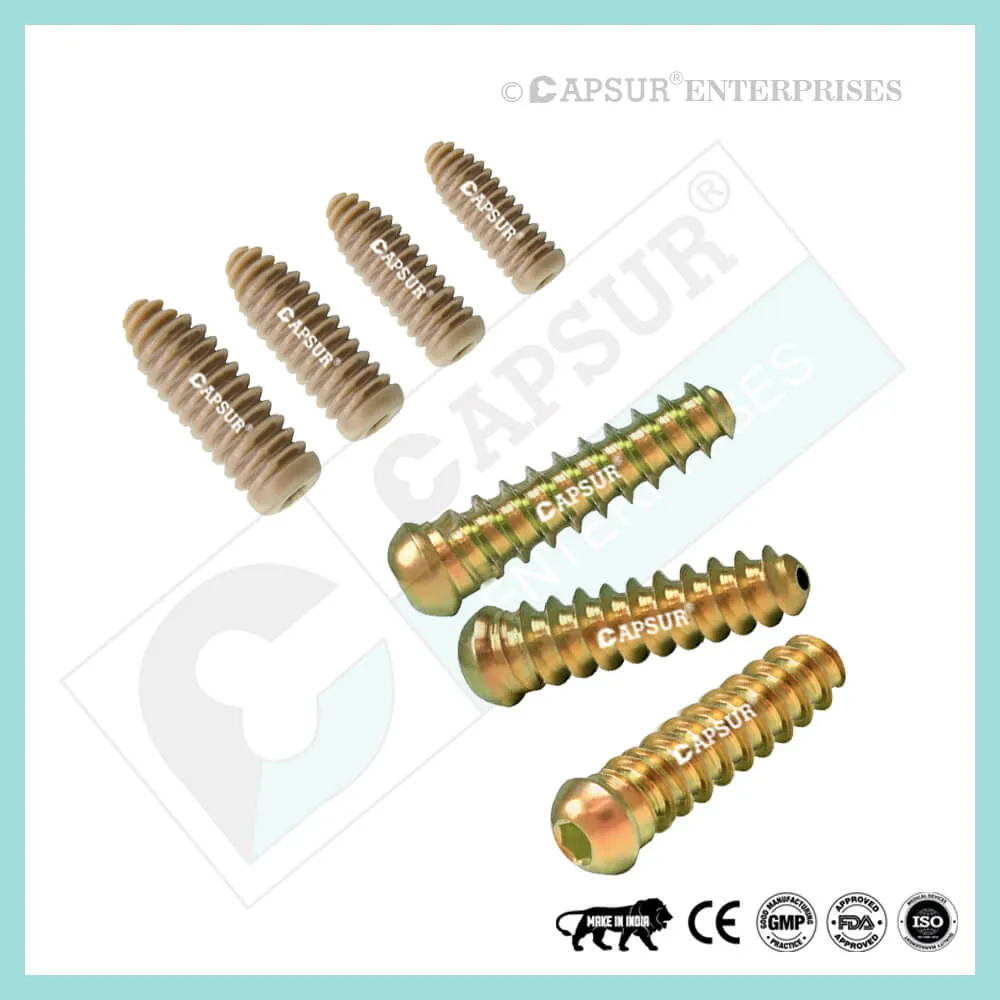
Different Types of Screws including PFNA2 Blade
Locking Cortical Screws
- 2 mm Locking Cortical Screws
- 2.4 mm Locking Cortical Screws
- 2.7 mm Locking Cortical Screws
- 3.5 mm Locking Cortical Screws
- 5 mm Locking Cortical Screws
Cortical Screws
- 1.5 mm Cortical Screws
- 2 mm Cortical Screws
- 2.4 mm Cortical Screws
- 2.7 mm Cortical Screws
- 3.5 mm Cortical Screws
- 4.5 mm Cortical Screws
Locking Cancellous Screws
- 3.5 mm Locking Cancellous Screw
- 4 mm Locking Cancellous Screw
- 5 mm Locking Cancellous Screw
- 6.5 mm Locking Cancellous Screw
Cancellous Screws
- 3.5 mm Cancellous Screw
- 4 mm Cancellous Screw
- 6.5 mm Cancellous Screw
Locking Cannulated Screws
- 4 mm Locking Cannulated Screw
- 5 mm Locking Cannulated Screw
- 6.5 mm Locking Cannulated Cancellous Screw
- 7.3 mm Locking Cannulated Cancellous Screw
Cannulated Screws
- 3.5 mm Cannulated Screws (Cortical Thread)
- 4 mm Cannulated Cancellous Screws
- 4.5 mm Cannulated Cancellous Screws
- 6.5 mm Cannulated Cancellous Screws
- 7 mm Cannulated Cancellous Screws
- 7.3 mm Cannulated Cancellous Screws
Headless Screws Full Thread
- 2.5 mm Headless Compression Screws Full Thread
- 3 mm Headless Compression Screws Full Thread
- 3.5 mm Headless Compression Screws Full Thread
- 4 mm Headless Compression Screws Full Thread
- 4.5 mm Headless Compression Screws Full Thread
- 5 mm Headless Compression Screws Full Thread
- 5.5 mm Headless Compression Screws Full Thread
- 6.5 mm Headless Compression Screws Full Thread
Headless Screws Partially Thread
- 2.5 mm Headless Compression Screws Partially Thread
- 3 mm Headless Compression Screws Partially Thread
- 3.5 mm Headless Compression Screws Partially Thread
- 4 mm Headless Compression Screws Partially Thread
- 4.5 mm Headless Compression Screws Partially Thread
- 5.5 mm Headless Compression Screws Partially Thread
- 6.5 mm Headless Compression Screws Partially Thread
- 7.5 mm Headless Compression Screw Partially Thread
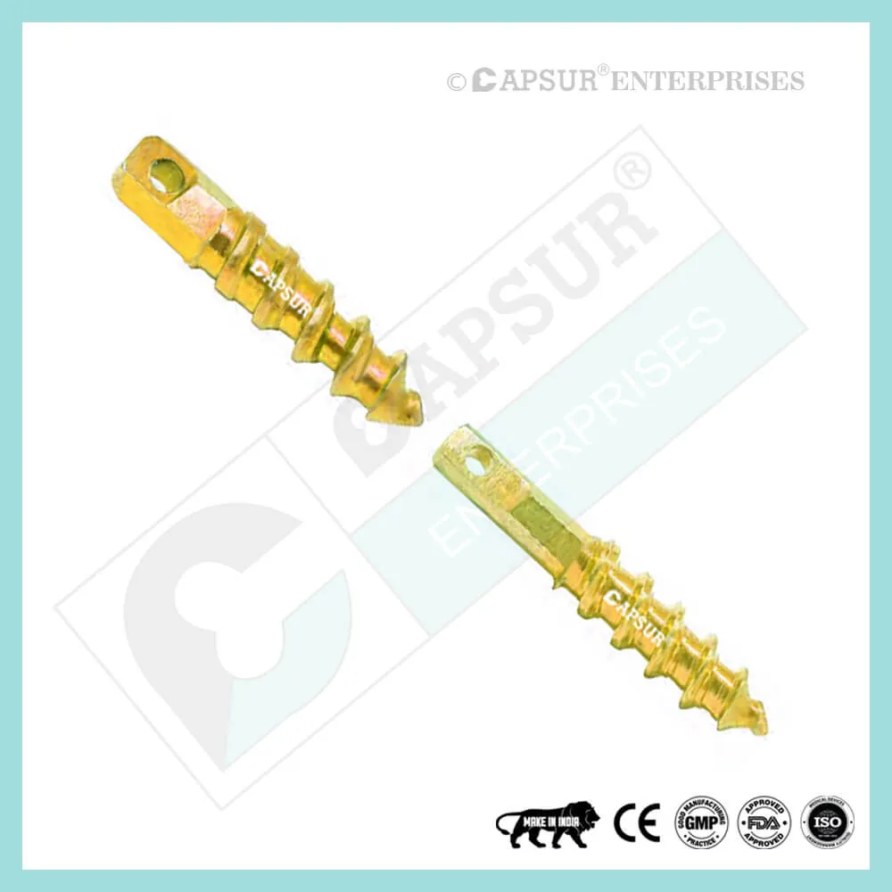
Interlocking Nail Screws
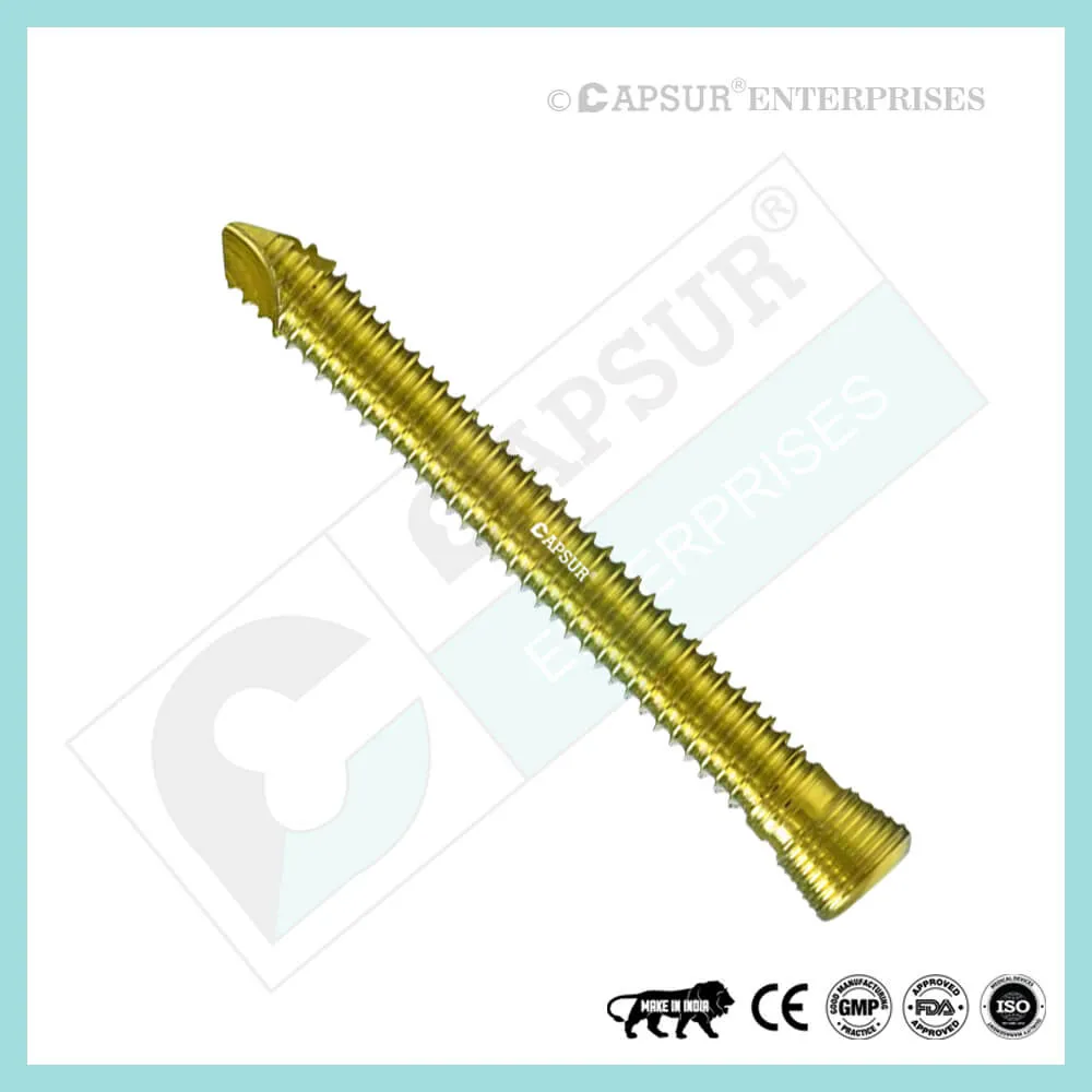
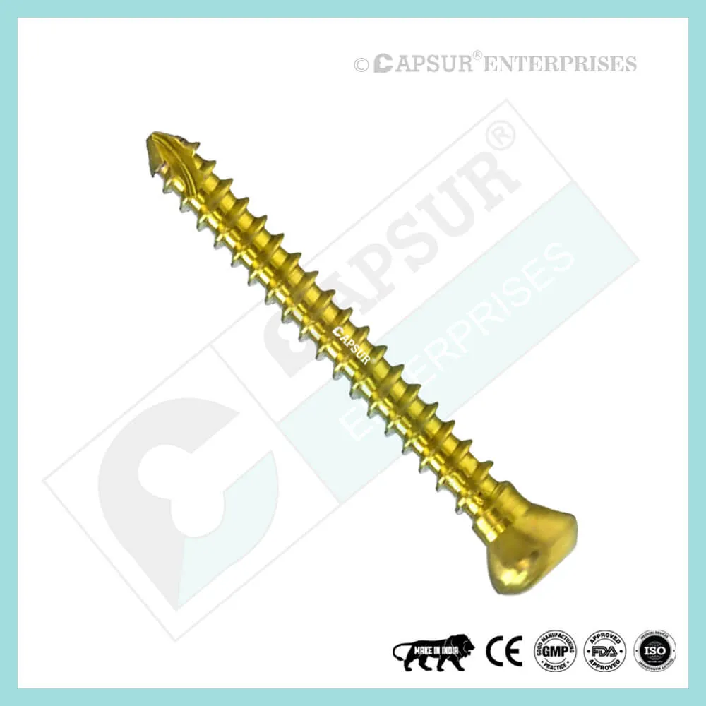
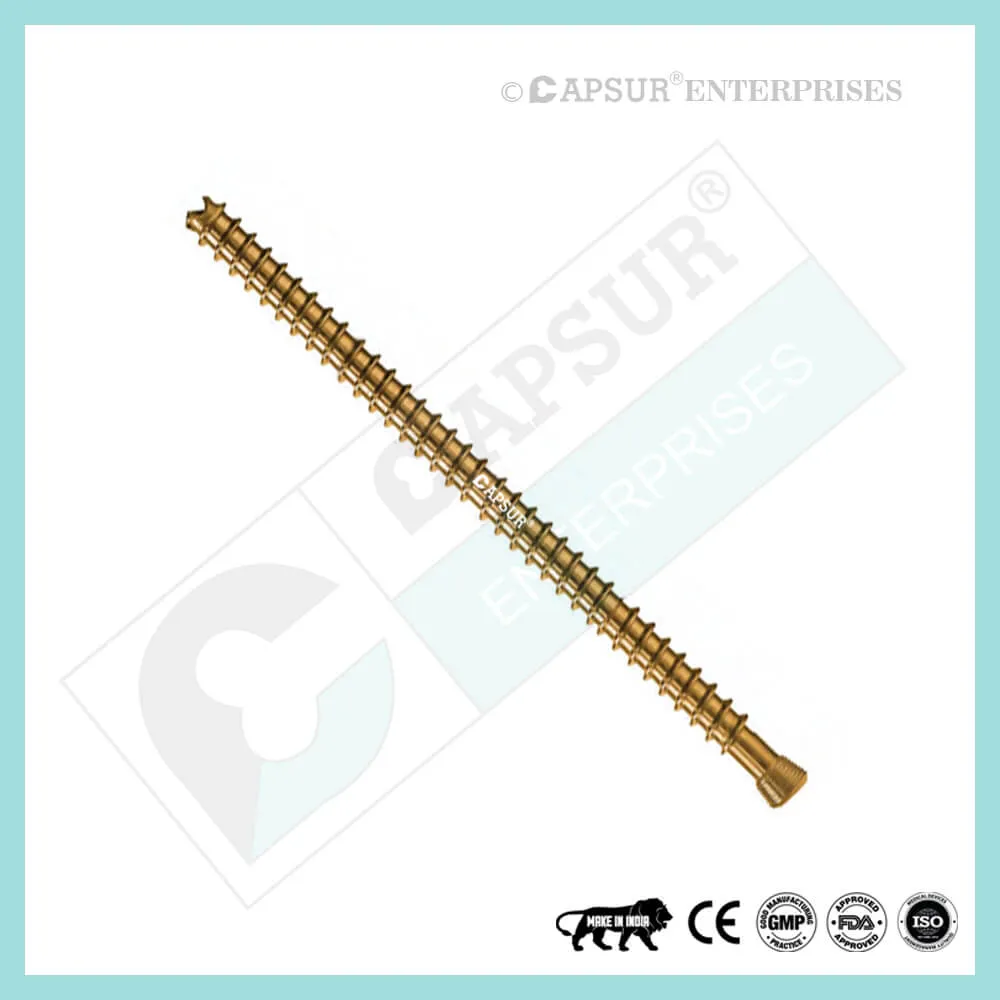
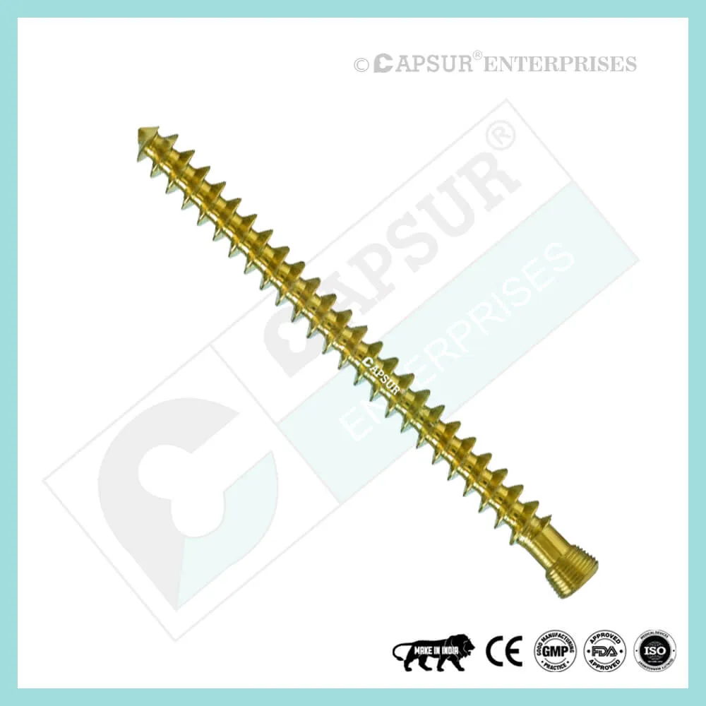
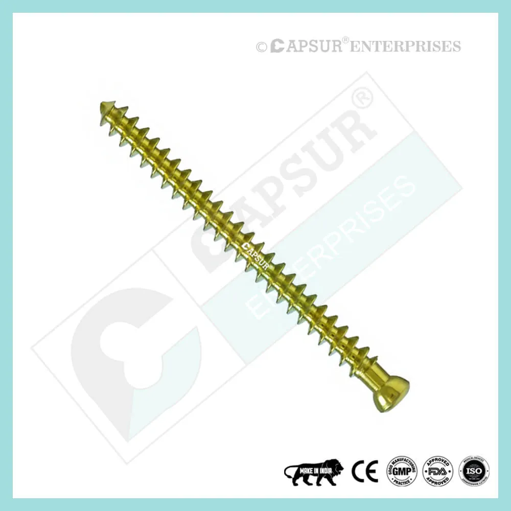
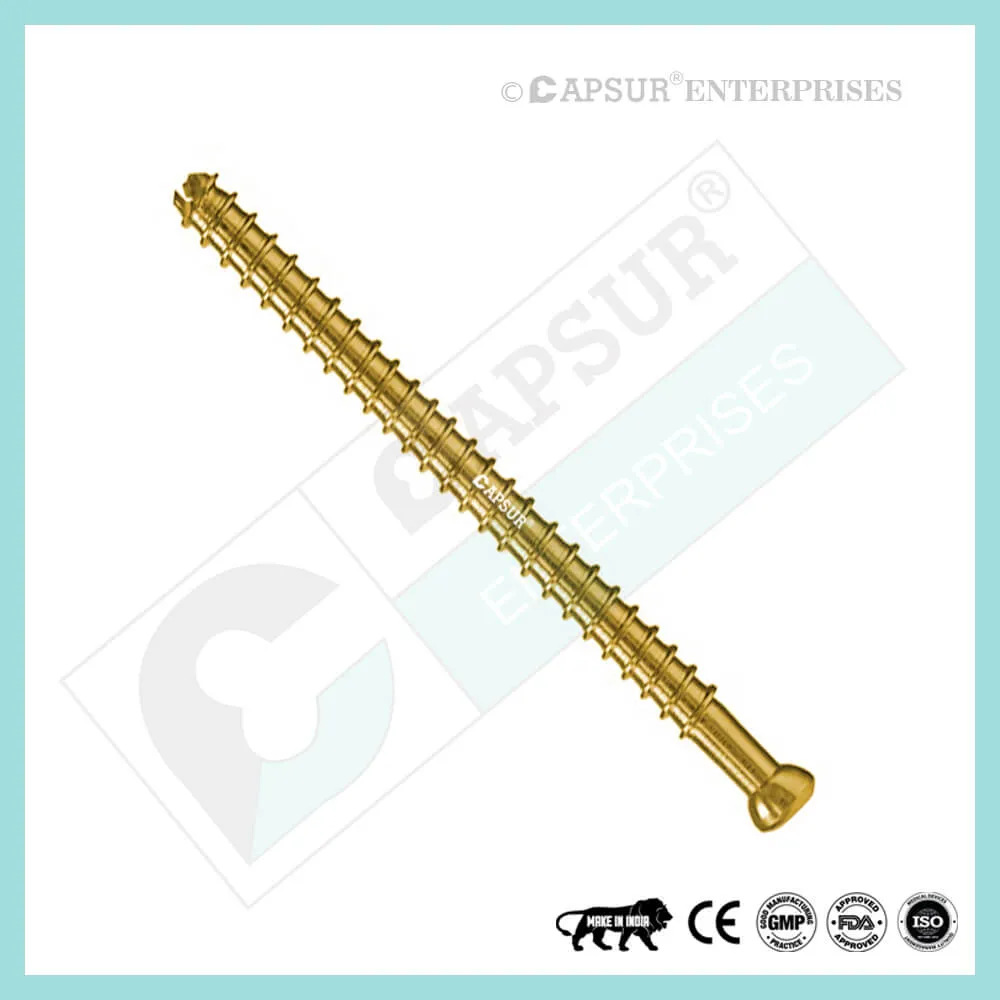
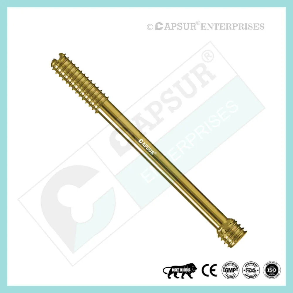
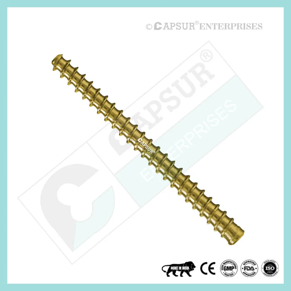
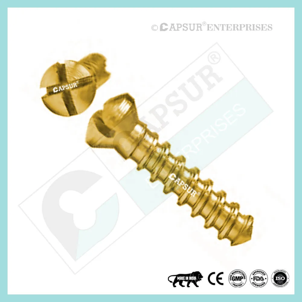
PFNA2 Blades
PFNA Blades
- 8 mm Proximal Cannulated Bolt
- 6.4 mm Proximal Cannulated Bolt
- 4.9 mm Locking Bolts
- 3.9 mm Locking Bolts
- 3.4 mm Locking Bolts
Interference Screws
- 5 mm Interference Screw
- 6 mm Interference Screw
- 7 mm Interference Screw
- 8 mm Interference Screw
- 9 mm Interference Screw
- 10 mm Interference Screw
Herbert Screws
- 2.5 mm Cannulated Herbert Screws
- 3 mm Cannulated Herbert Screws
- 3.5 mm Cannulated Herbert Screws
- 4.5 mm Cannulated Herbert Screws
- 5.5 mm Cannulated Herbert Screws
- 6.5 mm Cannulated Herbert Screws
Craniomaxillofacial Screws
- 1.5 mm Screw Craniomaxillofacial
- 2 mm Screw Craniomaxillofacial
- 2 mm Locking Screw Craniomaxillofacial
- 2.5 mm Screw Craniomaxillofacial
- 2.5 mm Locking Screw Craniomaxillofacial
- 2.8 mm Screw Craniomaxillofacial
- 2.8 mm Locking Screw Craniomaxillofacial
- 2.7 mm Emergency Screw
Malleolar Screws
- 3.5 mm Malleolar Screws
- 4.5 mm Malleolar Screws
The most frequently used orthopedic implants are bone screws. For various types of bones, there are numerous types and sizes of screws. The majority of bone screws are constructed from titanium or stainless steel alloys. When determining screw mechanics, it’s important to consider the outer diameter, root diameter, thread pitch, and angle.
The outer diameter of screws is commonly used in orthopedics to describe them; for instance, a “PFNA2 Blade” has an outer diameter of 10.5 mm. The linear distance covered by a screw during one complete turn is known as the pitch of the screw. With each full turn, the screw moves forward by a distance equal to the space between the threads. Cortical screws have more threads because they have a lower pitch. Given the fragility of the bone, cancellous bone screws have a deeper screw to increase surface area and enhance purchase.
Screws work by converting the torque applied to tighten them into internal tension and elastic responses in the bone around them. The fracture fragments that the screw is holding together are compressed as a result. Typically, screws are inserted into holes that have been drilled to the same diameter as the root and are either self-tapping or have been tapped (threaded) beforehand. The screws must be properly inserted into the proper size drilled hole and made to withstand the insertion torque levels anticipated in cortical bone because the torque to insert cortical bone screws can be high. Large, deep threads on cancellous bone screws allow them to securely hold the spongy bone. It is uncommon for a screw to fail during insertion due to the cancellous bone’s relatively low strength, but pull out can be problematic.
PFNA2 Blade Risk Factor
When assessing the prognosis in each case, contraindications—which may be partial or complete—must be taken into account. Under the following circumstances, alternative management strategies may need to be taken into account:
- infections that are systemic or local, acute or chronic.
- either localized, systemic, or chronic inflammation.
- serve as a dangerous vascular, nervous, or muscular disease.
- Bone defects that would prevent the implant from being properly anchored.
- All associated illnesses that might jeopardize the implant’s success and functionality.
Warnings and Precautionary for PFNA2 Blade
The surgeon and support staff should read the safety instructions in this document as well as any product-specific information in the product description, surgical techniques, and/or brochures before using the PFNA2 Blade.
Screws are designed, built, and produced with the utmost care using materials of the highest quality for medical use. If these high-quality screws are used properly, they guarantee the best working outcomes. As a result, the usage guidelines and safety advice below must be followed.
The incorrect use of a screw can result in injury to the operator, patients, or other people as well as tissue damage, premature wear and tear, instrument destruction, and instrument destruction.
The operating surgeon must actively participate in the medical care of their patients. The surgeon must have a complete understanding of the instruments, their limitations, and the surgical procedure. The surgeon and the surgical team are responsible for exercising caution in the selection and use of surgical instruments. Before using implants, adequate surgical training should be obtained.
Factors that could harm the operation’s success include:
- allergies to materials implanted.
- regional bone tumors.
- osteomalacia or osteoporosis.
- metabolic disturbances and systemic disease.
- drug and alcohol abuse.
- Excessive shock-producing physical activity that exposes the implant to blows and/or heavy loads.
- Patients who lack the mental capacity to comprehend and follow instructions from a doctor.
- Unhealthy overall.
- Potential Negative Effects
The most frequent side effects following implantation are as follows:
- screw loosening that may be caused by the implant’s tissue reaction or by the fixation site’s repeated loading.
- the two stages of infection.
- additional bone fracture brought on by abnormal stress or weakened bone structure.
- a hematoma or pressure-related pressure that causes temporary or permanent neural damage.
- Hematomas from wounds and slow wound healing.
- Venous thrombosis, pulmonary embolism, and cardiac arrest are examples of vascular disease.
- heterotopically ossifying.
- Due to the PFNA2 Blade’s presence, there is pain and discomfort.
- Implant mechanical failure, such as bending, loosening, or breakage.
- Implant migration leading to injury.
Preoperative Planning for PFNA2 Blade
Following a thorough clinical evaluation of the patient, the operation is planned. X-rays are also necessary to provide a clear picture of the bony anatomy and any associated deformities. Along with a full size of PFNA2 Blade, the appropriate implantation tools must be on hand at the time of the procedure.
The potential risks and complications related to the use of implants should be discussed with the patient by the clinician. If the patient has allergies to any of the implant materials, it is crucial to know this before surgery. Additionally, the patient needs to be made aware that the device’s performance cannot be guaranteed because problems may reduce its lifespan.
PFNA2 Blade Precautions
During reprocessing, verify that the instruments are functional and look for wear. Before using, replace any worn-out or broken instruments.
It is advised to use the tools designated for this screw.
Use caution when handling equipment, and put used bone-cutting tools in a sharps container.
Always use suction and irrigation to remove any debris that may be produced during implantation or removal.
PFNA2 Blade Warnings
When put through excessive force, PFNA2 Blades can break while in use. We advise that the broken part be removed whenever possible and practical for the particular patient, though the surgeon will ultimately decide whether to do so based on the risk involved. Be aware that implants lack the natural bone’s strength. Significant loads may cause implants to fail.
The user’s glove or skin may be pinched or torn by the sharp edges or moving joints of some instruments, screws, and cut plates.
Be sure to get rid of any fragments that weren’t fixed during surgery.
While the surgeon will ultimately decide whether to remove the implant, we advise that fixation devices be taken out as soon as it is safe and practical for the specific patient and after their purpose as a healing aid has been fulfilled. To prevent refracture, implant removal should be followed by adequate post-operative care.
PFNA2 Blade General Adverse Events
There are risks, side effects, and adverse events associated with all major surgical procedures. While there are many possible reactions, the following are some of the most frequent ones: issues related to anesthesia and patient positioning (such as nausea, vomiting, dental injuries, neurological impairments, etc.), thrombosis, embolism, infection, damage to nerve and/or tooth roots or other critical structures, such as blood vessels, excessive bleeding, damage to soft tissues, including swelling, abnormal scar formation, functional impairment of the musculoskeletal system, and pain.
| PFNA2 Blades |
|---|